
تبلیغات
موضوعات
جستجو
پیوندهای روزانه
لینک دوستان
- دریافت رایگان این قالب
- سایت عاشقانه ماندگار فان
- سایت عاشقانه عشق آفرین
- جامعه رادیو اماتوری ایران
- سازمان تنظيم مقررات و ارتباطات راديوئي
- شرکت اروم الکترونیک
- فروشگاه قطعات الكترونيكي
- ARRL • Devoted Entirely to Amateur Radio
- درددل های یک بازنشسته
- نخستین سایت آموزشی رادیو آماتوری در ایران
- نشریات آماتوری
- EP2MRD
- QRZCQ - The database for radio hams
- شناسه تخصيص نحوه دستورالعمل ايستگاه به ارتباط راديويي هاي ) Call Sign ( دستورالعمل ارتباط شناسه تخصيص نحوه ايستگاه به راديويي
- رادیو آماتوری
- کلوپ رادیو آماتوری ایرانیان
- ارسال لینک
صفحات جانبی
امکانات جانبی
 آمار
وب سایت:
آمار
وب سایت:
بازدید دیروز : 2
بازدید هفته : 2330
بازدید ماه : 13056
بازدید کل : 2427797
تعداد مطالب : 674
تعداد نظرات : 121
تعداد آنلاین : 1
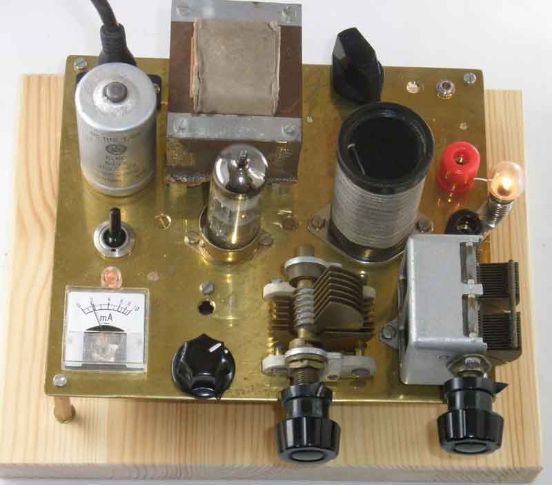
فرستنده لامپی
با سلام و تسلیت ایام شهادت سرور آزادگان جهان حسین ابن علی علیه السلام
مدار فرستنده لامپی ساده ای بدستم رسید جهت اطلاع عزیزان تقدیم می گردد
http://www.sm7ucz.se/AM_Transmitter/AM_transmitter.htm
ECL85 medium wave AM-Transmitter
Men det kunde lika gärna ha varit ECL80, ECL82, ECL84 eller ECL86

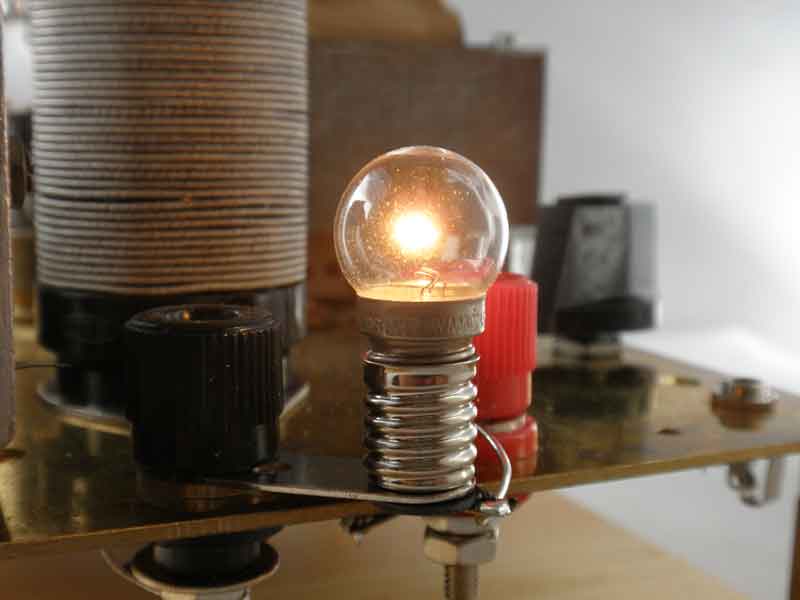
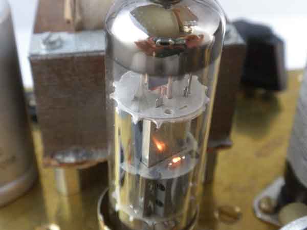
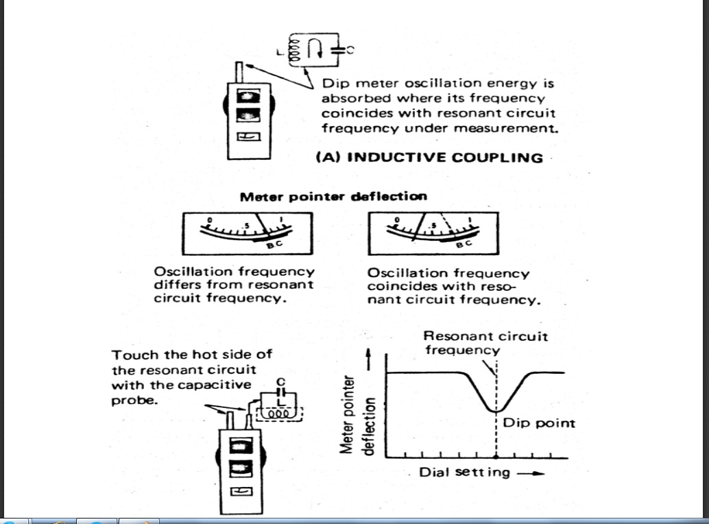
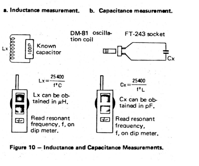
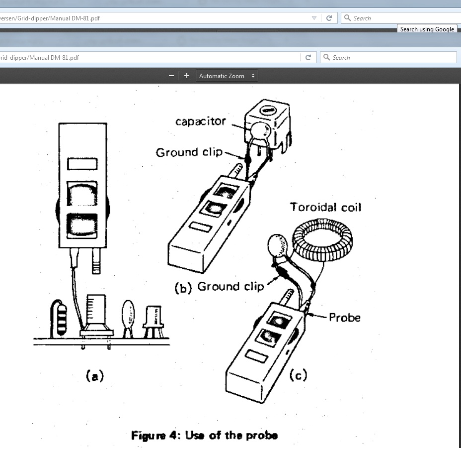
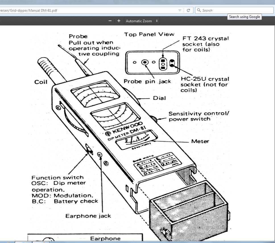
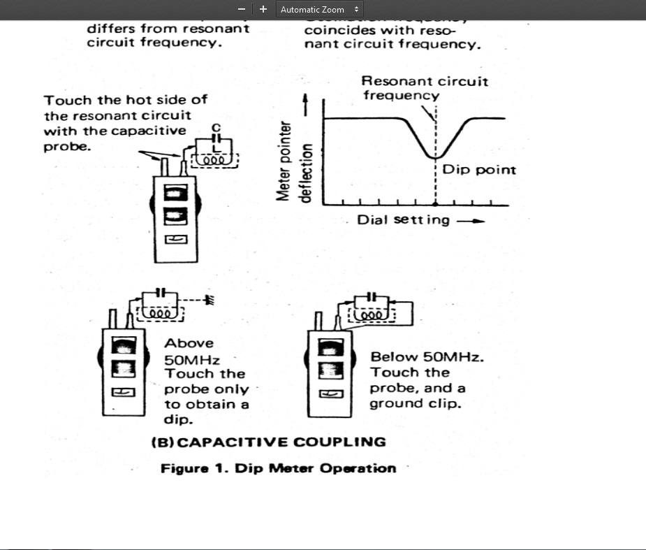
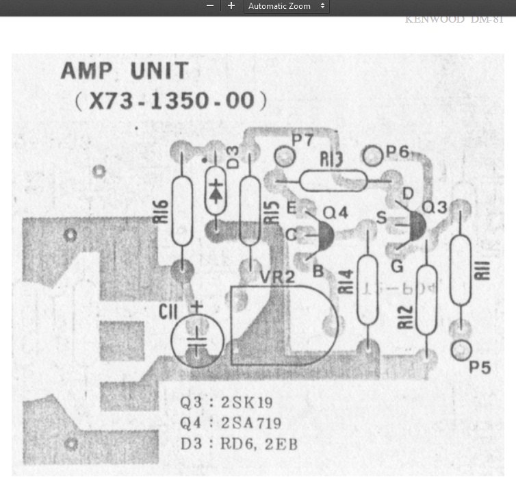
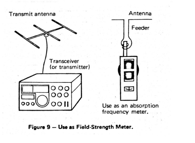
Grid dip meter
با سلام و تسلیت ایام شهادت سرور آزادگان جهان حسین ابن علی علیه السلام
یکی از ابزار لازم کارگاه رادیو آماتور دیپ متر می باشد که توضیحی چند به عرض می رسد
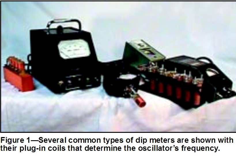
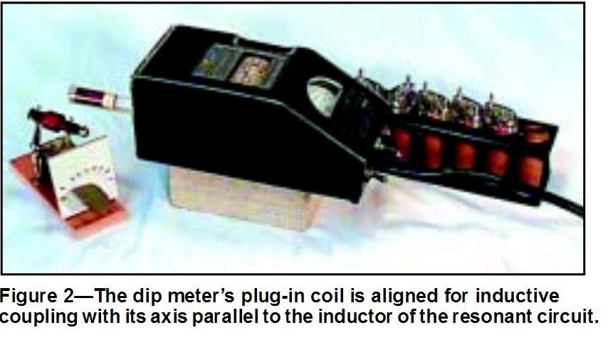
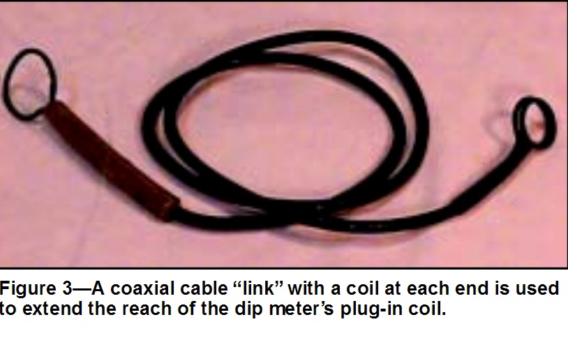
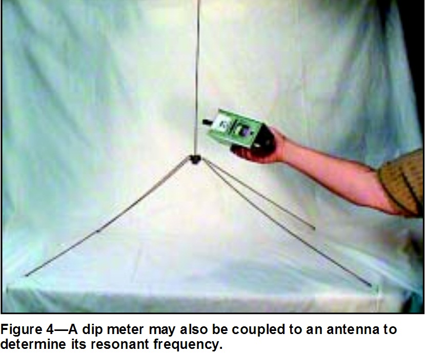
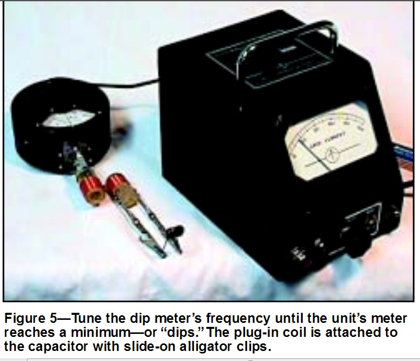
ادامه مطلب در ادامه مطلب
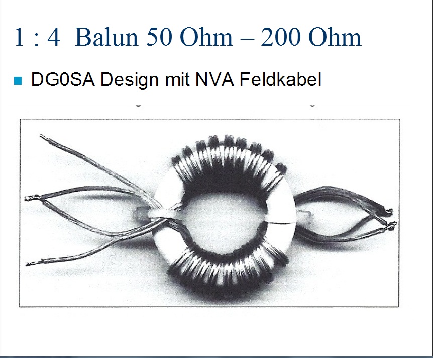
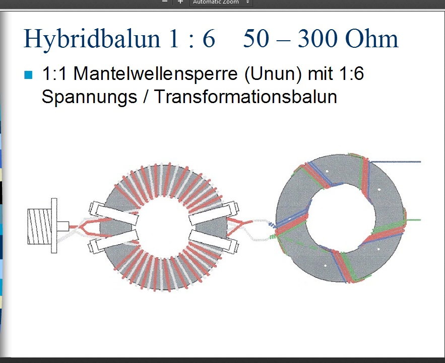
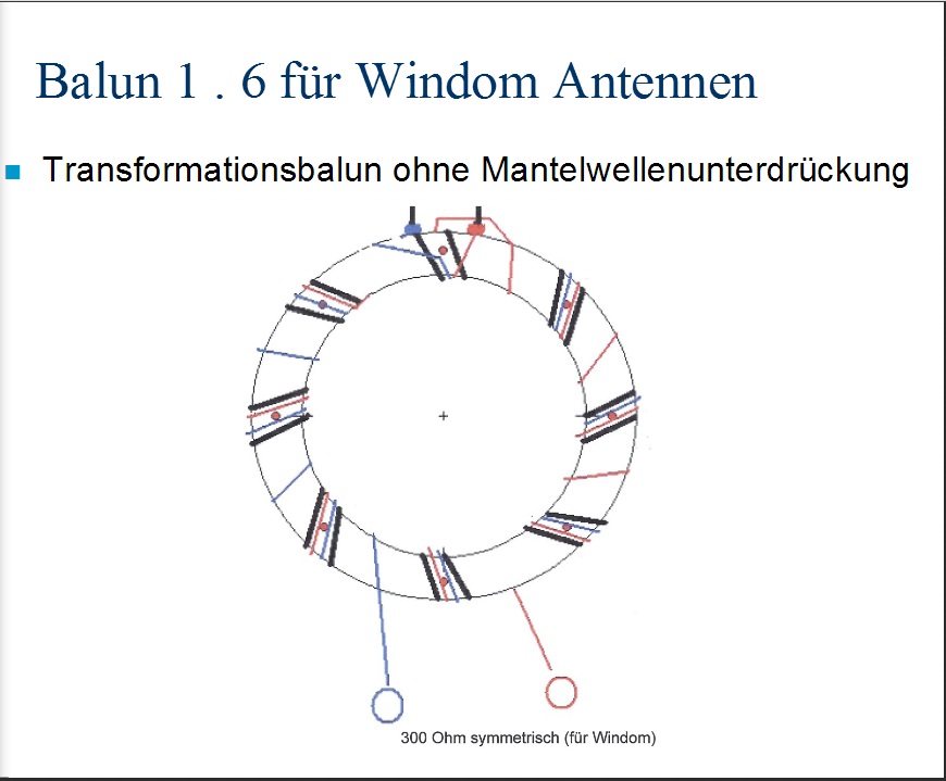
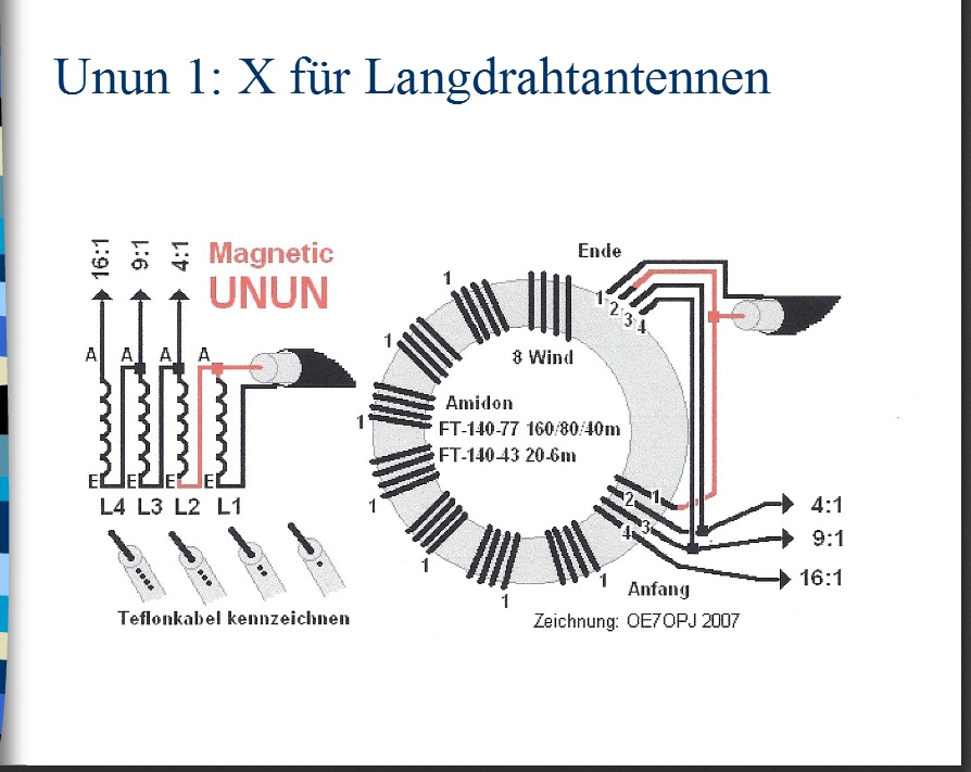
Maching Baloon
با سلام
http://www.darc.de/fileadmin/_migrated/content_uploads/Baluns__Ununs___Co_01.pdf
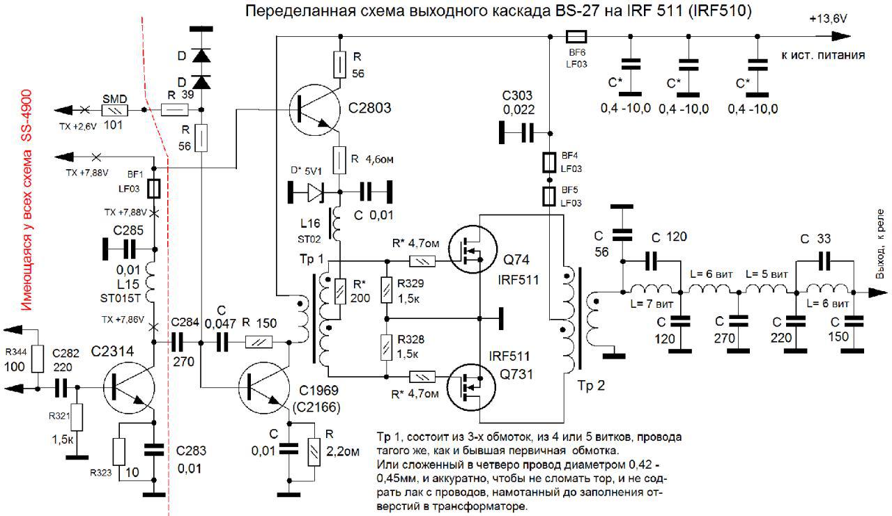
تغییر ترانزیستور 1969 تقویت قدرت رادیو به IRF510
با سلام و درود فراوان و تشکر بسیار از دوست و سرور عزیزم جناب مهندس فرشچی
مطلب فوق را ایشان در گروه رادیو آماتورها آورده بودند که بدلیل جالب بودن اینجا اراعه می شود


rf amplifer for racal tacticom hf radio
با سلام
یکی از دوستان در مورد مدار تقویت قدرت رادیوی راکال سینکال 30 پرسید که نقشه و عکس برد مدارچاپی آن تقدیم می گردد
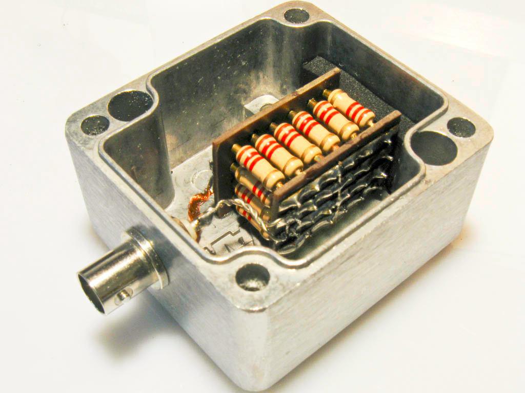
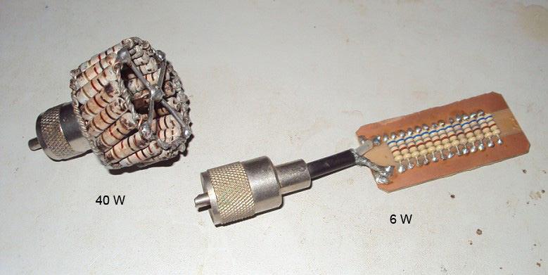
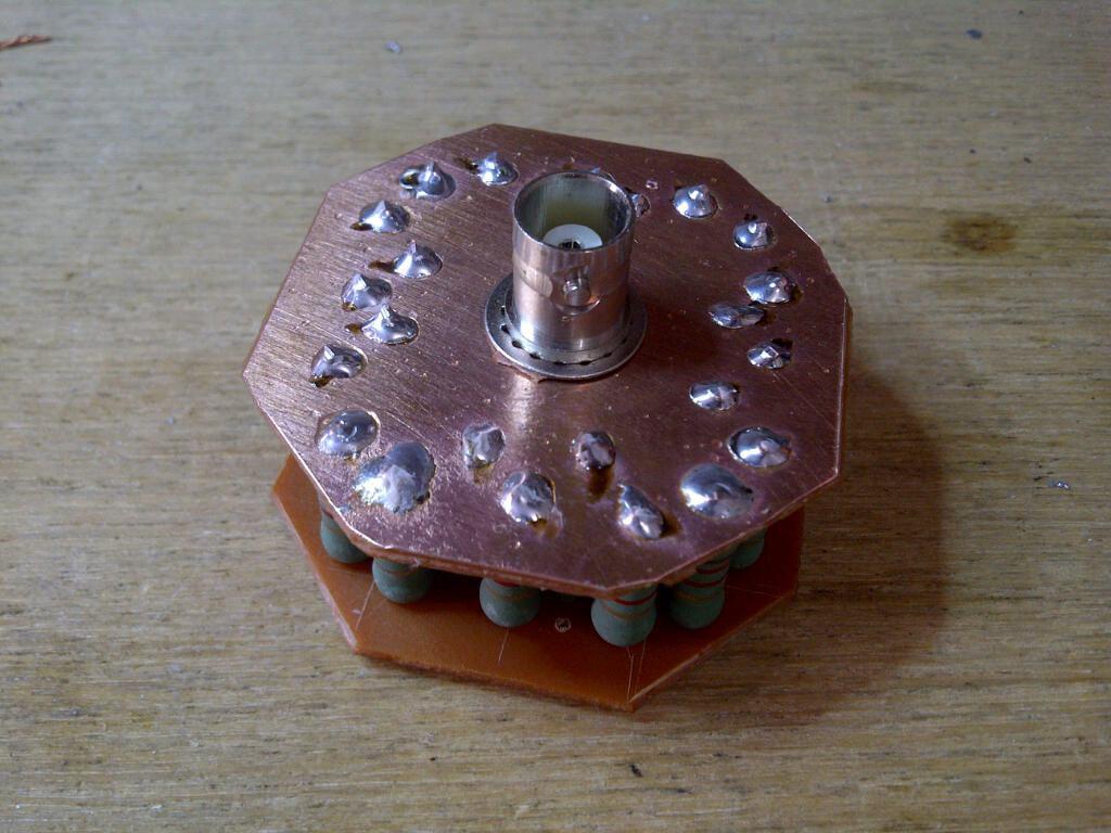
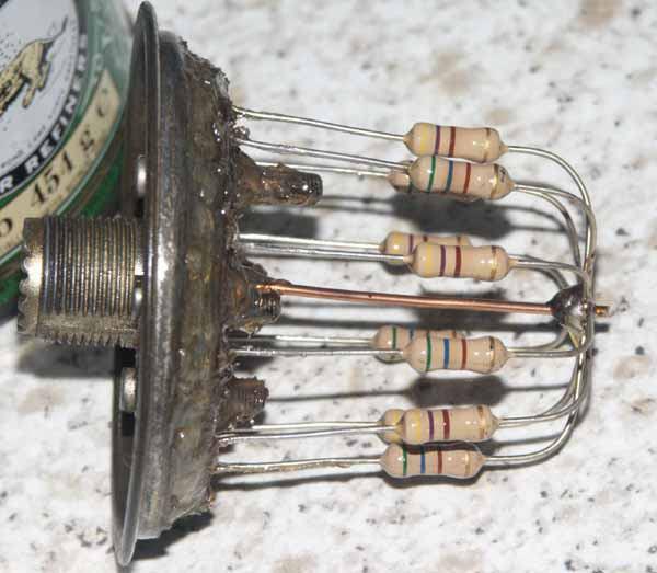
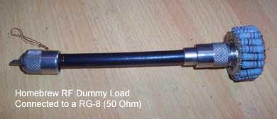
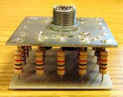
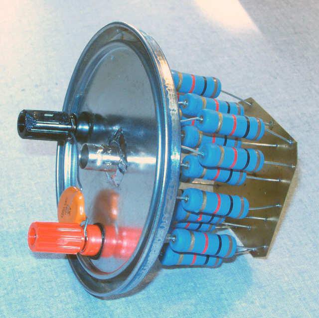
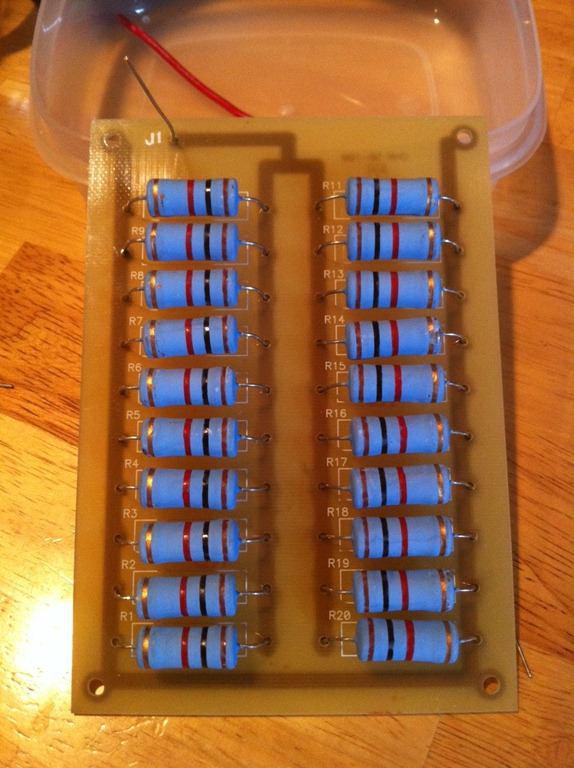
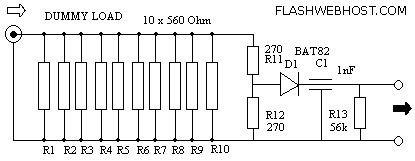
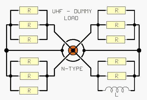
Dammy Load
با سلام
یکی از ابزار مهم کارگاه رادیو آماتوری بار مجازی یا دمی لود می باشد که چند نمونه آن ارائه می گردد
ارسال فایل فشرده مدارات لامپی
با درود و سلام و تبریک ایام
دوست گرامی مهندس سجاد گلچین پور فایلهای زیر را تهیه کردند که برای علاقمندان ارسال می گردد
http://s9.picofile.com/file/8268344418/4_830178914453160005.pdf.html
http://s8.picofile.com/file/8268344434/4_830178914453160006.pdf.html
عنوان مطالب مدارات لامپی است و چندین نمونه گیرنده و فرستنده را ارایه نموده اند
طرح های لامپی = گیرنده موج خیلی بلند-فرستنده آ ام لامپی - فرستنده اف ام لامپی -سوار بر امواج رادیو -فرستنده اف ام - فرستنده تلگراف - مبدل موج کوتاه -فرستنده و گیرنده نوری -
CW-SSB-transceiver direct conversion to 10 meters
http://www.diagram.com.ua/list/rst-kb0.shtml
For SSB transceiver and CW transmitting and receiving in the range 28 ... 29.7 MHz. The device is built by direct conversion circuit with a common mixer - a modulator for receiving and for transmitting.
Specifications transceivers:
1. The sensitivity in reception mode for the signal / noise ratio of 10 dB, not worse ........ 1 mV.
2. The dynamic range of the receiving path, as measured by the method dvuhsignapnomu about .... 80 dB
3. Receiving channel bandwidth at -3 dB .................................... 2700Gts.
4. Bandwidth unipolar radiation transmission ....................... 2700 Hz
5. The carrier frequency and the non-operating side band suppressed not worse than ............................. 40 dB
6. The transmitter output power in CW on 750m load ............................... 7 W
7. Disposed frequency oscillator 30 minutes after the warm-up not exceeding ........ 200 Hz / hr.
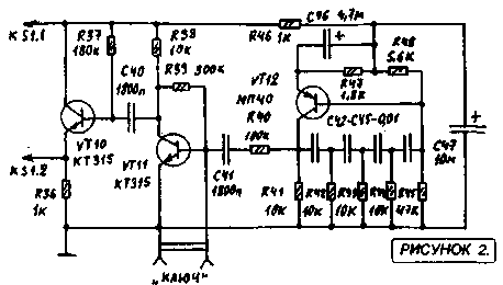
Schematic diagram of the transceiver (without telegraph node) is shown in Figure 1. The transceiver has separate receiving and for transmitting high-frequency and low-frequency paths common to both modes is the mixer-oscillator and modulator VFO

Fig.1
Variable Frequency Generator (GPA) is made of two field-effect transistors and VT5 VT6 connection with a source driver. It operates at a frequency equal to half the frequency of the received or transmitted signal. When working at the reception and the transmission of the output circuits of the GPA is not switched, and does not change the load on the GPA. As a result, the transition from reception to transmission or vice versa, the frequency of the GPA is not rejected. Setting is made within a range by means of alternating air dielectric capacitor C10, which is part of the VFO loop. The SSB transmit mode, the microphone signal is amplified by the operational amplifier A2 and fed on to faeovraschatel elements L10, L11, C13, C14, R6, R7, which in the frequency range 300 ... 3000 Hz provides a phase shift of 90 °. The circuit L4 C5 serving total load mixers diodes VD1-VD8, allocated signal in the upper sideband range 28-29,7 MHz. High broadband faeovraschatel L8 R5 C9 in this range provides a phase shift of 90 °. Dedicated single-sideband signal through a capacitor C6 is supplied to a three-stage power amplifier transistors VT7-VT9.
Cascade pre-amplification and isolation of the mixer-modulator output circuit is formed on the transistor VT9. The high input resistance combined with low capacitance C6 provides a minimal impact on the power amplifier circuit.
In VT9 collector circuit switched circuit tuned at mid-range. The intermediate stage FET VT8 works in Class mode, "B", and the output stage in Class mode "C".
"U" -shaped low-pass filter on the L12 C25 and C26 clears the output signal from the high-frequency harmonics and ensures coordination of the output impedance of the output stage with impedance of the antenna. PA1 ammeter is used to measure current output transistor drain and indicates the correct settings "P" -filter.
Wire mode is provided by replacing the A2 amplifier sine wave oscillator frequency of 600 Hz (see Figure 2). Switching CW-SSB is done with S1. Telegraph key controls displacement VT11 preamp generator, and thus feed the low-frequency signal to the modulator.
CW-SSB-transceiver direct conversion to 10 meters
In receive mode, the power of the transmitter 42 on the stage is not supplied and the power amplifier and microphone amplifier are disabled. At this time, 12V voltage is applied to the cascade receive path.
The signal from the antenna is supplied to the input circuit L1 L2 C3 through the coupling coil, she agreed with the resistance of the circuit impedance of the antenna. On VT1 transistor RF amplifier made. The gain stage is determined by the bias voltage at its second gate (divider resistors R1 and R2). The load stage is L4C5 circuit connection RF amplifier stage with this circuit is carried out by means of the coil L3 Communications. With regard coil L5 signal is sent to a demodulator diode diodes VD1-VD8. The coils L8, L9 and L10 and the phase shifter is isolated L11 AF signal in the frequency band 300 ... 3000 Hz, which, via a capacitor C15 to the input of the operational amplifier A1. Strengthening of this circuit is determined by the sensitivity of the main transceiver in receive mode. The following AF amplifier transistor VT2-VT4, whose output signal is sent to the AF compact speaker volume B1 reception is controlled by the variable resistor R15.
In order to avoid loud clicks when switching modes "RX-TX" on UMZCH power transistor VT2-VT4 is served both in reception and transmission.
Most of the details of the transceiver is mounted on three printed circuit boards, pictures of which are shown in Figures 3-5. In the first board arranged the details of the input RF amplifier receiving channel (transistor VT1), the mixer parts - fazovraschayuschimi modulator circuits, as well as details of the local oscillator. The second board - low-frequency cascades on chips A1 and A2 and transistor VT2-VT4. on the third board amplifier power transmission path is placed. The board with mixer-modulator, RF amplifier and the GPA is screened.
Chassis transceiver has a width of 350 mm and a depth of 310 mm. On the front cover removed all controls and sockets for microphone and telegraph key. The speaker is also installed on the front panel, it is screwed M3 screws through the rubber grommets Mode Switching "RX-TX" is made pedal that -Includes disables voltage 42 V and operates two electromagnetic relays, one of which switches the antenna and the second voltage is 12 V at the receiving tract. Relay coil voltage feed 42, and de-energized include reception mode (RX).
Sockets for connecting the antenna, the pedals and the source 12 are located on the rear panel.
For the transceiver power used by the base stationary power supply unit, which supplies a constant stabilized voltage of 12 V with a current of 200 mA and a constant voltage of 42 V unstabilized with currents up to 1 A.
The transceiver used fixed resistors MLT on the power indicated in the diagrams.
Trimmer SDR-4a. Contour Ceramic capacitors necessarily, Trimmers CPC-M. Electrolytic capacitors K50-35 type or similar import. Variable capacitors oscillator and output circuits - with air dielectric.
For the winding contour coils RF amplifier, mixer and the transmitter using ceramic scaffolds 9 mm with cores trimmers SCR-1 (can be plastic frames from the paths UPCHI old tube TVs, but their thermal stability is much worse than that of the ceramic). Low-frequency coil mixer -modulyatora L8 and L9 are wound on the ring core of ferrite K16h8hb 100NN or more high-frequency (100VCH, 50VCH). The coils L10 and L11 are wound on the carcasses of the OB-30 2000IM1 ferrite. On these cores wound coil generators and erase bias semiconductor reel tape recorders.
Transistors KP303G KP303 can be replaced with any letter index or KP302. The transistor can be replaced by KP350A KP350B, KP350V or KP306. The transistor KP325 - by KT3102. Powerful FETs KP901 and KP902 can be any letter indices. For UMZCH fit any silicon and germanium (respectively) transistors corresponding structure. KD503 diodes can be replaced by KD514, adiod D9 to D18.
Establishing transceiver begin with GPA By adjusting core L7 and the inclusion of additional capacitor (5-30 pF) in parallel C10 generator is necessary to achieve the overlap in frequency 14.0 ... 14.85 MHz.
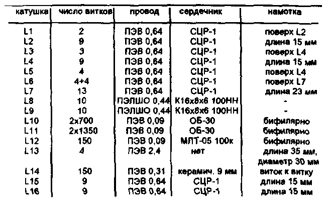
Table 1
CW-SSB-transceiver direct conversion to 10 meters
The work of the local oscillator can be checked using the RF frequency and RF voltmeter the voltage at each of the L6 coil halves should be 1.6 ... 1.8 V. If it is not included in these limits - you need to choose the number of coils L6. Now you need to go to the setup microphone amplifier and mixer - modulator. Do not connect the power 42 to apply 12V voltage at the output 7 A2 and test the functionality of the amplifier. Adjust the sensitivity can be the selection of the nominal value R31.
To set the mixer - the modulator need an oscilloscope, millivolt and tone generator (GZCH). With millivoltmeter and adjust the generator L11 contour C 14 on the frequency of 480 Hz, then loop L10 C13 on the frequency of 1880 Hz. Log phase shifter is disconnected from the capacitor C1S and C41, and the outputs from the L8 and L9 coils. Sign "X" and the oscilloscope AF generator output is connected to a connection point L10 and L11 coils. By the oscilloscope input "V connect SI L10 junction with the generator signal is fed to a frequency of 480 Hz In the oscilloscope display should be straight line sloping If instead the ellipse -... You need to fine tune the loop L11 S14.Zatem to input" Y "connected connection point L11 C12 and, in the same way check setting L10 C13 to the frequency of 1880 Hz. Thereafter, to the input of the oscilloscope "X" instead of the input of the phase shifter are connected free of its output. The channels of the oscilloscope sets the same gain. GZCH tuned to the frequency of 1880 Hz. The resistors R6 and R7 temporarily replace variable to 1 kW. Turn the R6 engine to achieve the appearance of the screen circumference. Then, setting GZCH 480 Hz is chosen in the same way the resistance of the resistor R7.
The setting is correct if the frequency change of the output GZCH in the range of 300 ... 3000 Hz on the oscilloscope screen, a circle will continue.
Resistor R5 achieve the best possible suppression of the lower sideband.
input circuit setting and L4C5 circuit to produce high frequency range. Then, sequentially energizing the power amplifier stages set up in the middle of the circuits L16 and L15 C34 C32 range. Setting the output stage is performed in the equivalent antenna connected - resistor 75 Ohm 10 W (you can solder the battery of four parallel connected resistors 2W 300 Ohm each).
Setting UMZCH comes to setting the selection of resistor R16 to the emitter voltage VT3 and VT4 equal to half the supply voltage.
Author: Bortko B .; Publication: N. Bolshakov, rf.atnn.ru
سایت دانلود رایگان
با سلام
ادرس ذیل سایت بسیار مناسب رایگان جهت در یافت نقشه و اطلاعات اکثر وسایل الکترونیکی منجمله فرستنده گیرنده ها و مجلات و کتب می باشد
http://www.diagram.com.ua/english/library/funkamateur-magazine/funkamateur-magazine.php?row=1
http://www.diagram.com.ua/library/elektronika-usiliteli/elektronika-usiliteli.php?row=1
http://www.diagram.com.ua/english/library/handbooks-rcomp-motorola/
ورود کاربران
عضويت سريع
پشتيباني آنلاين
آمار
خبرنامه
آخرین نطرات کاربران
 جواد یاور مطلق - درود
 بلا بدور باشه مهندس !
انشالله همیشه سرحال سالم تندرست باشید !
پاسخ:با درود و سپاس از لطف شما دوست گرامی بدرود - 1403/1/29
یک هم وطن - من بدون مدار این رادیو ساختم باصدای واضح و بلند بدون برق و باطری پاسخ:باتشکر از لطفتان امیدوارم بقیه دوستان هم همت کنند و دست به اچار و هویه شده خودشان بسازند و لذت ساختن را ببرند چون در داشتن لذت نیست هنر ساختن است - 1402/6/13
AEC - دروداستاد ممنون خیلی خوب و عالی
 پرویز مهرزاد - سلام درود جناب عبداحق عزیز بسیار خوشحالم که وب سایت شما با مطالب مفید وعالی فعال شده است.
پاسخ:باسلام و تشکر از لطف و مرحمت شما دوست عزیز و گرامی - 1400/8/28
پرویز مهرزاد - سلام ودرود استاد عبدالحق عزیز بسیار خوشحالم که سایت جنابعالی بامطالب جدید وعالی دوباره فعلیتش را شروع نموده است.پاسخ:با سلام تذکر بجا و بموقعی بود بسیار متشکرم - 1400/8/28
ایزدی - یه مشکلی داره این طرح. کل سلف ها با هم 12. 7 میکرو میشه که با خازن 270 پیکو، فرکانس مرکزی فیلتر 2.7 مگا هرتز می شه. کمترین سلف هم (0.1 میکرو) با همون خازن 270 پیکو 30 مگاهرتز رو رد می کنه. بنا بر این نیازی به خازن های دیگه نیست. دوستان دیگه نظرشون چیه.پاسخ:باسلام و تشکر کل خازن ها و سلفها برای فرکانس 1800کیلو که ابتدای باند رادیو اماتوری است کم است و بسختی تنظیم می شود اما برای 3500 بله زیاد است - 1399/8/24
هومن - سلام .علت استقبال نکردن در خور توجه همین نا واردیست .این مطلب بسیار گنگ و پر از اشتباه هست پاسخ: سلام بنده هم ضمن تائید نظر شما درخواست می کنم مطلب کامل تر و بهتر و درست تر را بفرمائید بنده بنام خودتان درج و منتشر نمایم
پاسخ:https://t.me/joinchat/AAAAAEJj30AwLGIyi_UQ3g مدارات لامپی - 1396/12/17
علی - سلام شما مکتبی و انقلابی هستید درسته ؟پاسخ: سلام بهیچ عنوان و تقریبا هیچ جائی من چنین ادعائی نکرده ام اما این همه شهید و زخمی و جانباز و اسیر و زحمت و فعالیت برای حفظ انقلاب و سرزمین عزیزمان ایران خیلی حرام لقه گی و بی اصل و نصبی می خواهد که چشم خودرا ببندیم و از این اب و خاک حمایت و به این مردم عشق نورزیم حالا شما اسم انرا هرچه دوست دارید بگذارید نظرتان محترم است - 1396/12/17
هومن - سلام بنده یکی از علاقمندان لامپ هستم . و 10 سال اخیر را بر روی مدارات لامپی کار کردم .با سرچ اینجا را پیدا کردم .می خواستم ببینم در زمینه مخابرات فعالیت لامپی در ایران هست ؟
این مطلب راجب لامپ واقعا توجه مخاطب علاقمند را جلب می کند ؟
من فکر می کنم نویسنده اصلا راجب لامپ حس خوبی ندارد .عذر خواهی می کنم
پاسخ:سلام دوست عزیز از صراحت و فصاحت بیان شما خوشحالم مطلبتان راجع به نویسنده مطلب لامپ کمی کم لطفی و شاید سخت گیری در بر دارد نویسنده مطلب استاد عاملی بزرگ رادیو اماتوری ایران هستند و مطلب را بی اندازه ساده و اسان گفتند چون اکثر جوانها از لامپ و ولتاژ کار ان وحشت داشته و تقریبا هیچ نمی دانند اما ظاهرا شما در مورد لامپ مطلع و ازموده هستید لذا برخود نگیرید شما هم اگر در مورد لامپ و یا مطالب استاد عاملی نقد و نظری دارید بسیار خوشحال می شوم مکتوب بفرمایید تا در همان بخش یا در بخش جدید بنام خودتان منتشر شود
پاسخ:https://t.me/joinchat/AAAAAEJj30AwLGIyi_UQ3g - 1396/12/16
سعیدی - سلام استاد بنده بی جواب ماندم پاسخ:با سلام و پوزش از تاخیر طبق تجربه دوستان این مدار به دلیل نامرغوب بودن قطعات نو موجود در بازار معمولا در ابتدا کار نمی کند لذا بتوصیه استاد عاملی بهنر است از قطعات اوراقی رادیو و ضبط ها استفاده شود قطعات معمولا در گیر این رادیو ابتدا ای سی سویچ یا کلید زنی است که یک مدل خاصش برای مدار مناسب است و مدلهای دیگر فرکانس کار و ولتاژشان مناسب نیست درمورد ای سی مدولاتور و دمدولاتور 3028 این ای سی هم بشدت مورد شک و شبهه است در موردی باتعویض 5 عدد ای سی دو عدد که بهتر بود در مدار بکار گرفته شد لذا بهترین روش استفاده از مرحله مرحله و گام بگام کار کردن رادیو است ضمن انکه اگر فرستنده کار بیفتد گیرنده هم کار خواهد کرد و بالعکس لذا شما می توانید مدار را از میکروفون در حالت فرستنده یا بلندگو در حالت گیرنده شروع نمایید و اگر مسیر سیگنال جدا باشد در نقشه شما می توانید از تقویت صدا شروع کرده و به دمدولاتور رفته و سپس به فیلتر و بعد میکسر وی اف او و در اخر به فیلتر تنظیم باند بروید و حد اکثر سیگنال و حساسیت را بدست اورید پس فیلتر های رادیویی یا بقول شما توکو ها قسمت اخر تنظیم و تعقیب مدارتان است اگر شد برای اطلاع شما و سایر دوستان مدار را در حالت گیرنده و فرستنده جدا اراعه خواهم داد یا با رنگ مسیر سیگنال را جدا می کنم که راحت تر باشد اگر شما عضو تلگرام هستید در یکی از گروه های رادیو اماتوری بیایید و مستقیما با دوستان سازنده و استفاده کننده رادیو تماس گرفته راهنمایی شوید اگر نه ادرس ایمیلتان را بدهید تا راهنمای مونتاژ را برایتان بفرستم
پاسخ:http://py2ohh.w2c.com.br/trx/ararinhamontagem/montandoararinha.htm
راحل مونتاژ و تست مدار است - 1396/11/5
آرشیو
- شهريور 1404
- تير 1403
- مهر 1402
- ارديبهشت 1401
- دی 1400
- آبان 1400
- ارديبهشت 1399
- اسفند 1397
- آذر 1397
- آبان 1397
- خرداد 1397
- ارديبهشت 1397
- فروردين 1397
- اسفند 1396
- بهمن 1396
- دی 1396
- آذر 1396
- آبان 1396
- شهريور 1396
- مرداد 1396
- تير 1396
- خرداد 1396
- ارديبهشت 1396
- فروردين 1396
- اسفند 1395
- بهمن 1395
- دی 1395
- آذر 1395
- آبان 1395
- مهر 1395
- شهريور 1395
- مرداد 1395
- تير 1395
- خرداد 1395
- ارديبهشت 1395
- فروردين 1395
- اسفند 1394
- بهمن 1394
- دی 1394
- آذر 1394
- آبان 1394
- مهر 1394
- شهريور 1394
- مرداد 1394
- تير 1394
- خرداد 1394
- ارديبهشت 1394
- فروردين 1394
- اسفند 1393
- بهمن 1393
- دی 1393
- آذر 1393
- آبان 1393
- مهر 1393
- شهريور 1393
- مرداد 1393
- تير 1393
- خرداد 1393
- ارديبهشت 1393
- فروردين 1393
- اسفند 1392
- بهمن 1392
- دی 1392
- آذر 1392