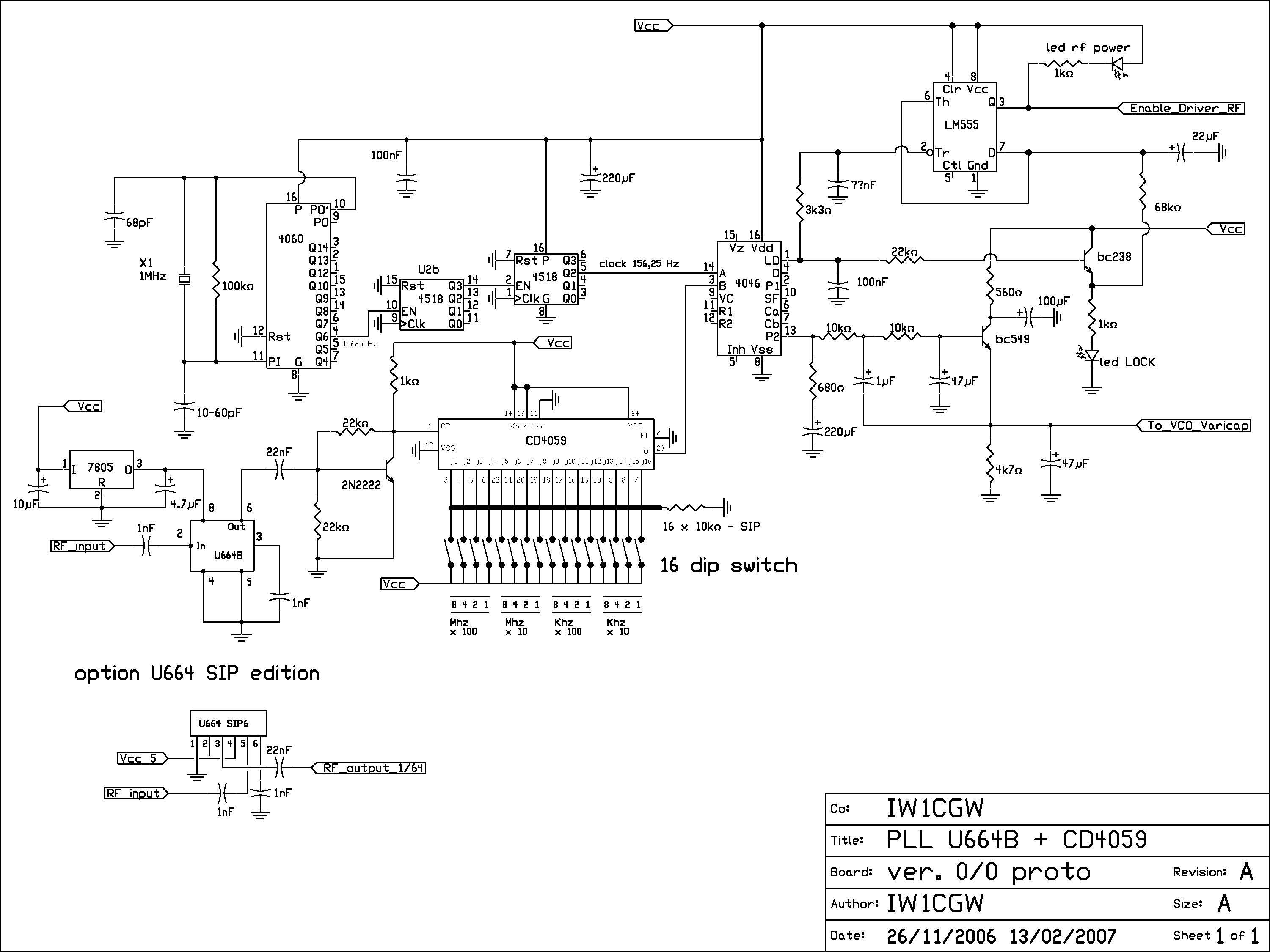
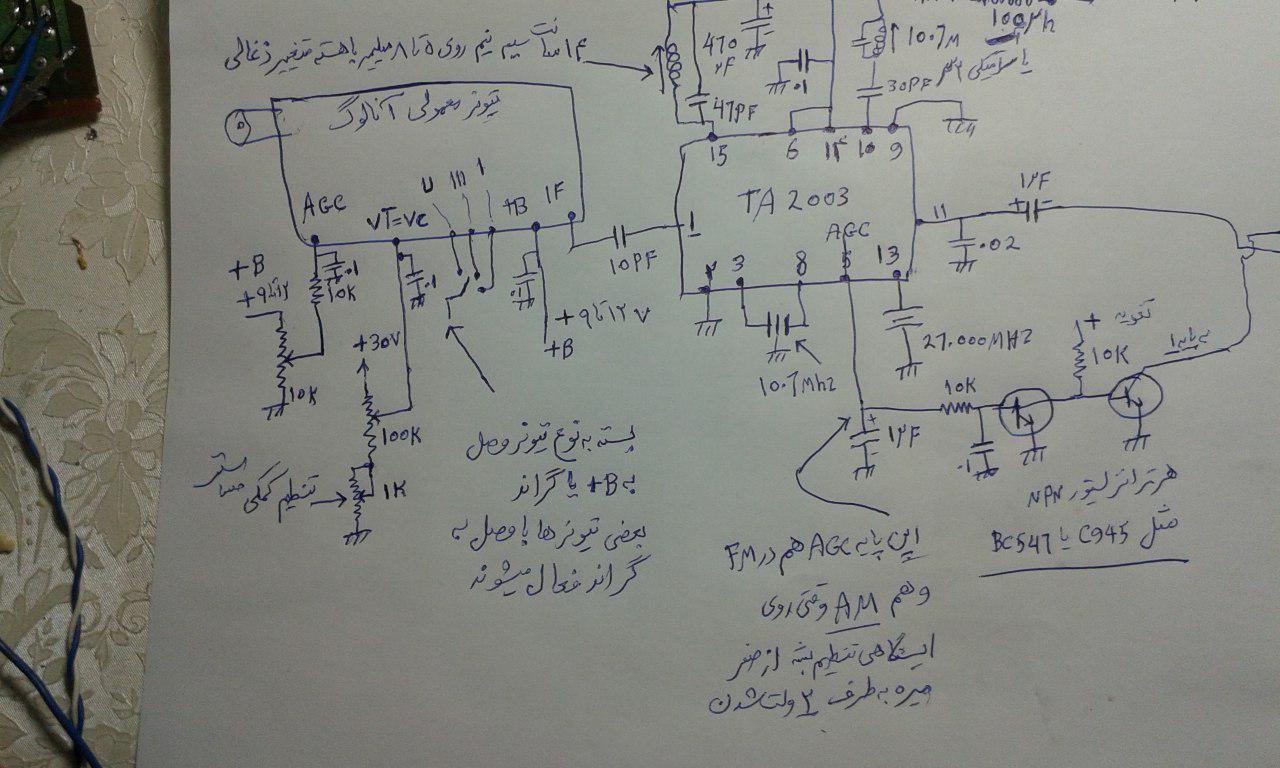
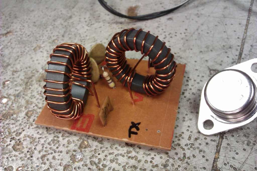
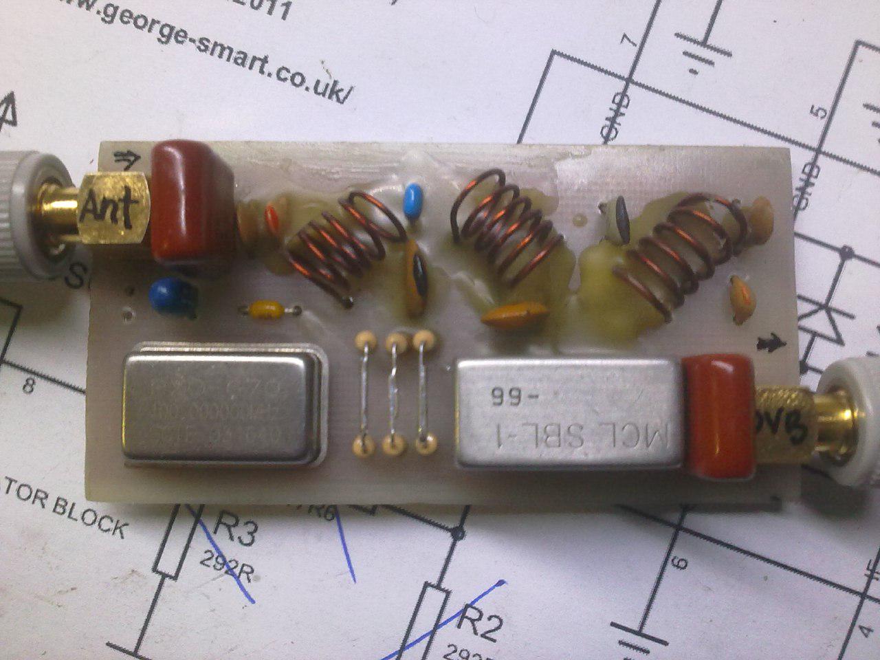
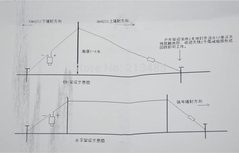
.

تبلیغات

موضوعات

جستجو

پیوندهای روزانه

لینک دوستان
- دریافت رایگان این قالب
- سایت عاشقانه ماندگار فان
- سایت عاشقانه عشق آفرین
- جامعه رادیو اماتوری ایران
- سازمان تنظيم مقررات و ارتباطات راديوئي
- شرکت اروم الکترونیک
- فروشگاه قطعات الكترونيكي
- ARRL • Devoted Entirely to Amateur Radio
- درددل های یک بازنشسته
- نخستین سایت آموزشی رادیو آماتوری در ایران
- نشریات آماتوری
- EP2MRD
- QRZCQ - The database for radio hams
- شناسه تخصيص نحوه دستورالعمل ايستگاه به ارتباط راديويي هاي ) Call Sign ( دستورالعمل ارتباط شناسه تخصيص نحوه ايستگاه به راديويي
- رادیو آماتوری
- کلوپ رادیو آماتوری ایرانیان
- ارسال لینک

صفحات جانبی

امکانات جانبی
 آمار
وب سایت:
بازدید دیروز : 3155
بازدید هفته : 15872
بازدید ماه : 18518
بازدید کل : 2250728
تعداد مطالب : 673
تعداد نظرات : 121
تعداد آنلاین : 1
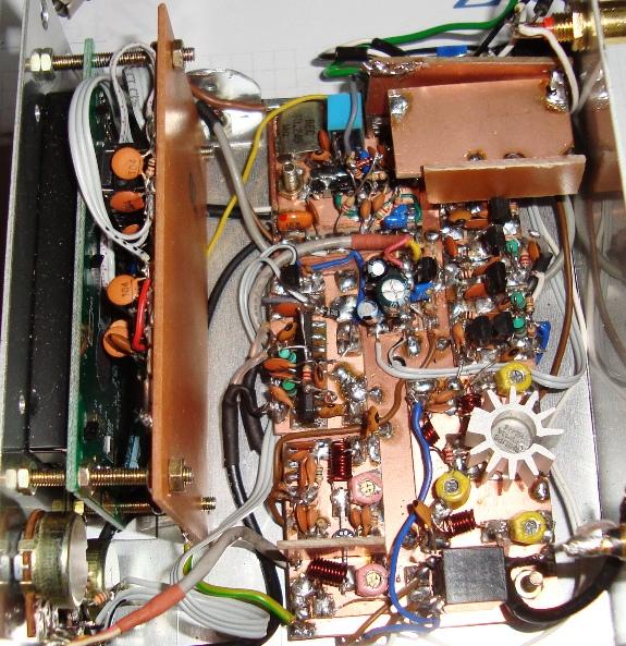
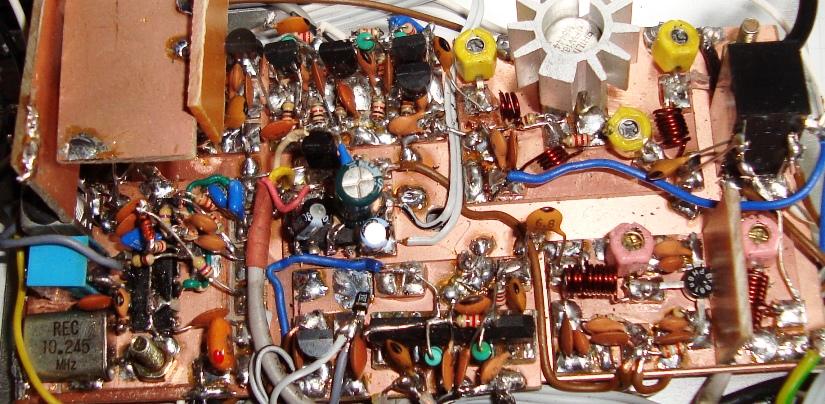
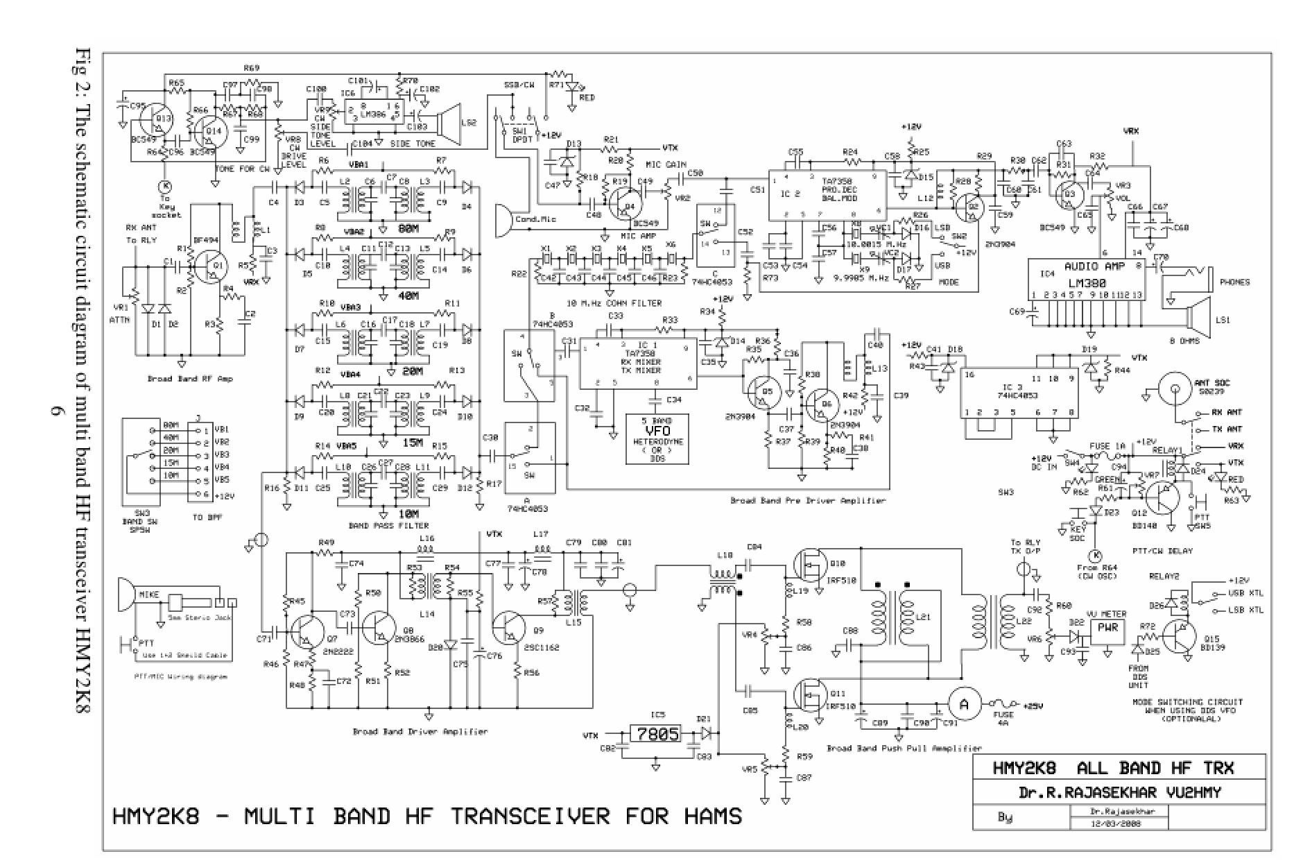
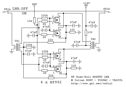
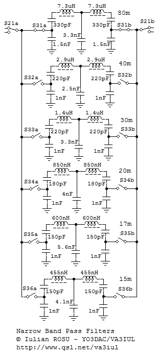
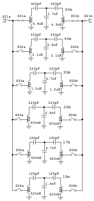
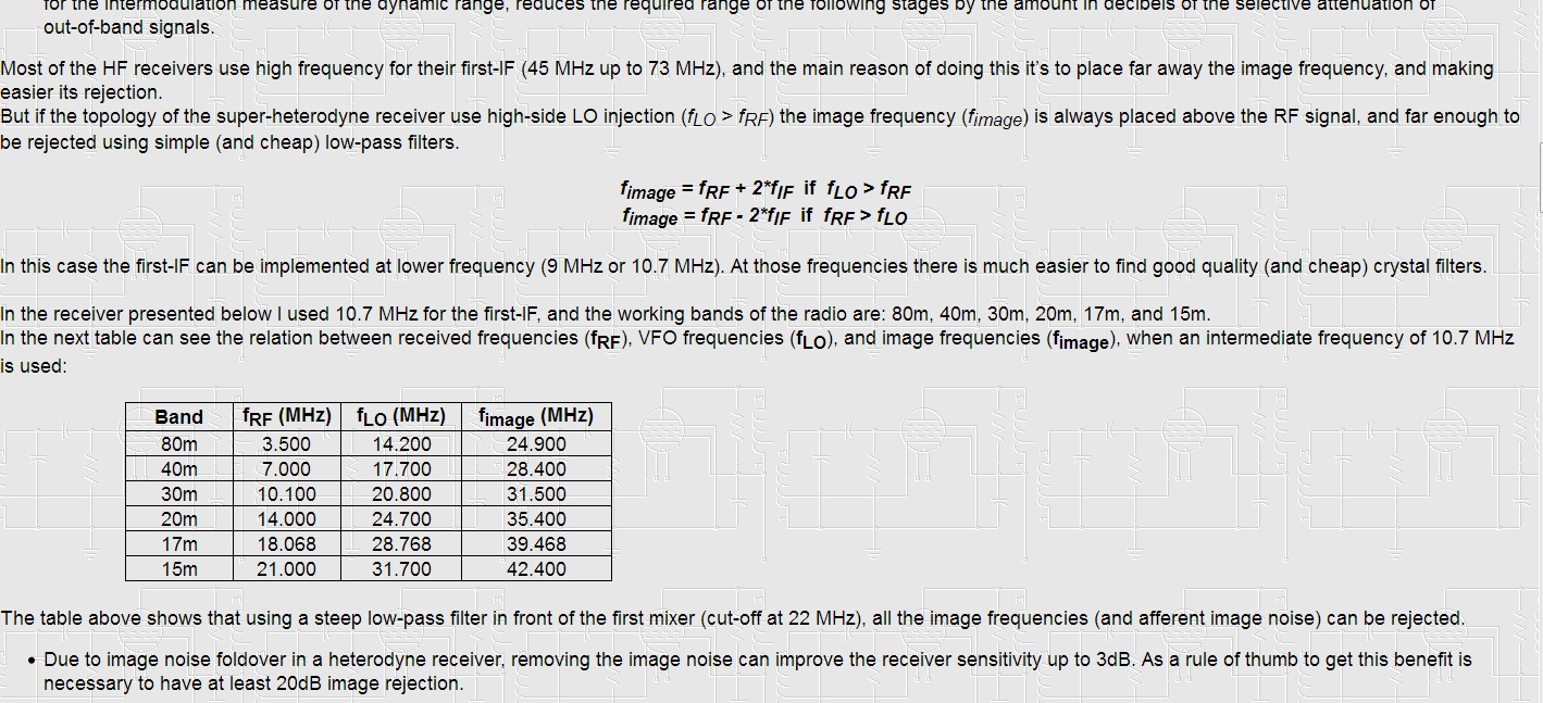
Low Noise Floor SSB Transceiver for 80m to 15m
با سلام و ارزوی قبولی طاعات و عبادات و تبریک پیروزی تیم ملی فوتبال و راهیابی ایران به جام جهانی
توضیحات در ادامه مطلب
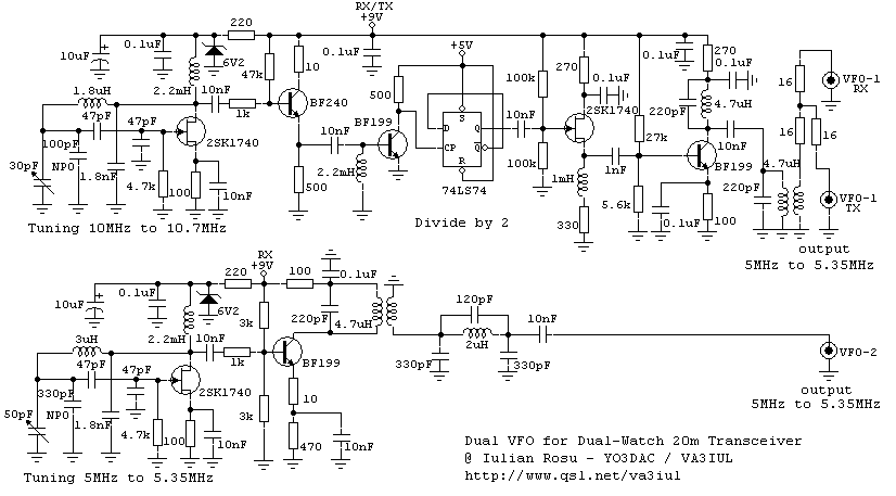
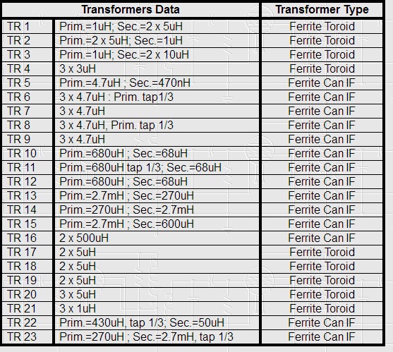
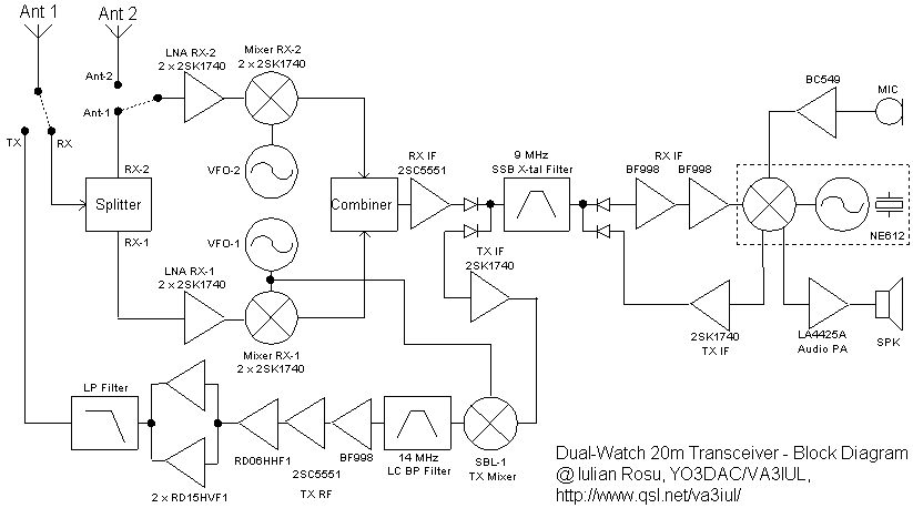
فرستنده گیرنده 20 متر دو فرکانسه
با سلام و ارزوی قبولی طاعات و عبادات
طرح فوق از دو نوسانساز فرکانس متغیرVFO استفاده کرده و هم زمان دو فرکانس را کنترل می کند ایده جالب و کار امدی است
کانال طرح ها و مدارات الکترونیک پارسی
با سلام و ارزوی قبولی طاعات و عیادات و تبریک ولادت امام حسن مجتبی (ع)
ادرس کانال تلگرامی مطالب مهم و طرح های رادیو اماتوری برای رادیو اماتورهای عزیز ایرانی
https://t.me/joinchat/AAAAAEO1feO9dPDbwdVs8A
اموزش اندازه گیری امپدانس کابل های کواکسیال ناشناخته
مهندس سجاد گلچین پور مطلبو ذیل رو ارسال کردند که بسیار جالب است و ضمن تشکر از ایشان در ذیل می آید:
اموزش اندازه گیری امپدانس کابل های کواکسیال ناشناخته
سلام به همه ی دوستان رادیو اماتور عزیز
مطالب نوشته شده برگرفته از یک کلیپ از یک رادیو اماتور خارجی هست که برای مشاهده اون میتونید از این لینک استفاده کنید.
http://www.circuitvalley.com/2011/08/accurate-lc-inductance-capacitance-meter.html
بعضی وقت ها به یه سری کابل که از قدیم خریده شدن و به دلایل مختلف مشخصاتی روی اون ها نوشته نشده برخورد میکنیم و نمیدونیم امپدانس اون ها چند اهمه و برای چه کاری مناسب هستن. یا روی بعضی کابل ها مقدار امپدانس کابل حک نشده و یا موقع خرید کابل شک داریم که ایا این کابل واقعا مرغوب هست و امپدانس 50 اهم داره یا نه.
اینجا روش تقریبی و ساده اندازه گیری امپدانس کابل رو توضیح بدیم.
وسایل مورد نیاز:
سیم چین یا کاتر
یک LC متر ساده (لینک) (میتونید کیت اماده رو از اقای علیپور یا قنبری خریداری کنید.)
روش کار بسیار سادست.
با سیم چین یا کاتر یک تیکه از کابل ناشناس رو قطع میکنیم. اصلا مهم نیست اندازه اون چقدر باشه ولی با توجه به دقت اندازه گیری دستگاه ما بین 30 تا 50 سانت کافی هست. نه بیشتر نه کمتر.
دستگاه رو روی حالت اندازه گیری ظرفیت خازنی قرار میدیم و شمارنده رو صفر میکنیم و ظرفیت خازنی بین مغزی و شیلد رو اندازه میگیریم و عدد رو بر حسب پیکو فاراد گوشه ای یادداشت میکنیم.
سپس دستگاه رو روی حالت اندازه گیری سلف قرار میدیم و در طرف دیگر کابل شیلد و مغزی رو به هم متصل میکنیم و شمارنده رو صفر میکنیم و از طرف دیگر کابل ظرفیت سلفی بین شیلد و مغزی رو اندازه گیری کرده و عدد بر حسب میکرو هانری یادداشت میکنیم.
سپس با استفاده از فرمول
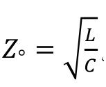
مقدار امپدانس رو بدست میاریم.
نکته بسیار مهم: در فرمول بالا حتما باید واحد ها یکسان باشن. یعنی حتما هر دو برحسب پیکو یا میکرو باشن. برای کسانی که ریاضی ضعیفی دارن میتونن فقط عدد ظرفیت سلفی رو که بر حسب میکرو هانری یادداشت کردن در 1000000 (یک و شش عدد صفر) ضرب کنن تا هر دو عدد بر حسب پیکو باشن. سپس اون دو رو بر هم تقسیم کرده و جذر بگیرن.
مقدار بدست اومده بعد از جذر گرفتن مساوی است با امپدانس کابل نامعلوم. در این روش با توجه به دقت اندازه گیری وسیله میشه امپدانس کابل رو با دقت کمتر از 2 اهم مشخص کرد.
مثال:
در یک اندازه گیری ظرفیت خازنی برابر با 37.2 پیکو فاراد و ظرفیت سلفی کابل برابر با 0.1 میکرو هانری شد. امپدانس کابل رو حساب کنید..jpg)
در پایان هم تشکر میکنم از اقای محمد عظیمی (EP2LMA) بابت معرفی کلیپ اموزشی.
نویسنده: سجاد گلچین پور
20m Loop Antenna
با سلام
http://213.114.137.49/antennas/20m_ant_00.htm
by Harry Lythall - SM0VPO
این رادیو اماتور عزیز در کشورخودشن سوئد در اپارتمان زیر در طبقه چهارم زندگی می کند و بسیار علاقمند به تماس در باند 20 متر بودند
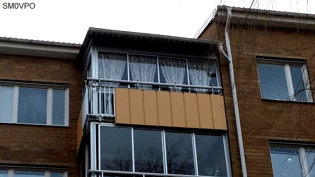
با توجه به محدودیت های موجود ایشون تصمیم گرفتند با امکانات موجود یک انتن ساده برای تماس در 14 مگا بسازند
لوازمی که مورد نظرشون بود عبارت بود از یکمتر لوله 15 میلیمتری پلاستیکی که برای کابل کشی درون ساختمان استفاده می شود و چند متر سیم برق نمره2/5
برای این کار ابتدا طول هرلوله 80 سانتیمتر جدا کرده و بعد از بستن انها بهم دیگر بصورت صلیب لوله ها را بافاصله 4 سانتیمتر از هم و 3دور برای سیم پیچ خروجی با فاصله یک سانت از نوک لوله سوراخ کردم در نتیجه فاصله سیم پیچ از هم 2/5 سانتیمترشد در یک سمت لوله عمودی با همان فاصله نیم دور سیم با اضافه کردن دو سوراخ چهارم جهت تغذیه از فرستنده قراردادم
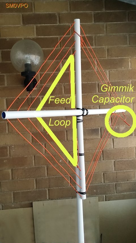
بعد از نصب قطعات نقطه کار انتن بصورت اماده در 14900 کیلو بدست امد و برای تنظیم دقیق انتن در انتهای سیم های بیرونی مقداری از سیم ها را دور هم پیچیدم تا خازنی تهیه شود که با تنظیم دقیق مقدار دور هم پیچیده شده فرکانس کار پایین امده و به 14175 رسید
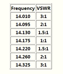
سر راه 5متر کابل انتنrg58 و انتن لوپ با استفاده از توروئید بکار رفته در منابع تغذیه کامپیوتر و سه رشته سیم با قطر یک میلیمتر تعداد 7 دور سیم بهم بافته را رد کرده و سر سیم هارا سری به هم وصل کردم
اول سر سیم الف بعد ته سیم الف به سر سیم ب بعد ته سیم ب به سر سیم ج و در اخر ته سیم جیم که به ترتیب شماره 1 و 2 و 3 و 4 شماره می گیرند
مطابق شکل زیر سیم ها به بالون متصل می شوند
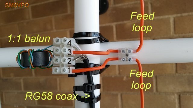
دو سر سیم تغذیه لوپ به اتصال یک و سوم وصل می شود مغزی کابل به سر چهار و بدنه کابل به سر دو اتصال خواهد داشت
کابل انتن هم از درون لوله نگهدارنده انتن لوپ عبور داده می شود
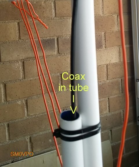
ابتدا و انتهای سه دور سیم لوپ را کمی بلند گرفته تا بروی هم تابیده شده و تشکیل خازن قابل تنظیم بدهند
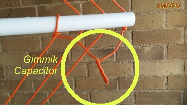
بعد با یک انتن انالایزر یا گرید دیپ متر یا برگشت سنج این تابیدگی را طوری انجام میدهیم که حداقل برگشت را در فرکانس 14175 کیلوهرتز داشته باشیم و انتن تنظیم و طول اضافه بریده و انتن اماده کار است
اصل گزارش در ادامه مطلب:
EH STAR (14 Mhz)
با سلام
این نوع انتن ها با اندازه بسیار کوتاه و انتشار ورتیکال و جای کم و. ساخت راحت ایده ال برای کار در اپارتمان و ساختمان های شهری هستند
http://iw3hzx.altervista.org/Antenne/EHSTAR/Ehstar.htm
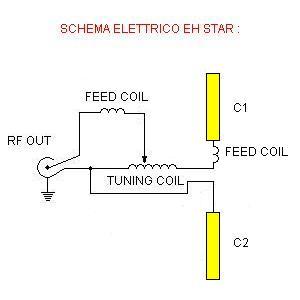
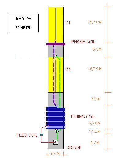


توضیح در ادامه مطلب:
Why do we use LSB below 10Mhz and USB above 10Mhz when operating SSB HF?
با سلام و عرض ادب
یکی از سوال های اکثر رادیو آماتورها علت انتخاب LSB در فرکانس کمتر از 10مگا هرتز و استفاده از مود USB برای فرکانس بالاتر از 10 مگاهرتز در باند HF می باشد
توضیحات ذیل شاید روشنگر مطلب باشد
The changing of ISB sideband positions at 10 MHz actually has an engineering background.
In the earliest ISB exciters, it was found appropriate to change the final mixer scheme from subtraction to addition mixing at around 10 MHz due to spurious suppression concerns. This sometimes caused interoperability problems in international point-to-point ISB circuits.
To overcome this, a practice was formalized in 1959 by the ITU/CCIR as the Recommendation 249, which prescribed that the ISB sideband positions could either automatically or manually be interchanged when the output frequency went through 10 MHz. An often quoted reference where ISB exciter design considerations are handled with German thoroughness is W Kleische: "Fernbedienbarer Steuervorsatz für Kurzwellen-Nachrichtensender" in "Telefunken-Zeitung" December 1962.
Later advances in exciter design made this Recommendation obsolete, and later generations of exciters only had this facility as an option, and current production ISB equipment lacks it entirely.
http://ham.stackexchange.com/questions/1336/why-do-we-use-lsb-below-10mhz-and-usb-above-10mhz-when-operating-ssb-hf
AB1GA Ham Member QRZ Page
The standard operating practice for SSB is, as 'KLI says, to use LSB below 10 MHz, and USB above 10 MHz. This is not a regulation, nothing forbids you from using the "other" sideband, but then who would you talk to?
The convention is, so I've heard, largely historical, based on the design of an early SSB rig. The IF was 9 MHz, which is 5 MHz below the bottom of 20 meters and 5 MHz above the top of 80 meters. When mixed with a 5-5.5 MHz VFO, the sum frequency was at 14.0-14.5 MHz, which covered 20 meters, and the difference frequency was at 4.0-3.5 MHz, which covered 80 meters.
I wrote the 80 meter frequency range backward to indicate that with this approach the higher the VFO frequency, the lower the mixer output frequency. This also meant that if you started with an upper sideband signal on 9 MHz, you still had a USB signal on 20, but an LSB signal on 80, and thus the convention was born.
Now, with the digital modes, all bets are off. I've heard old RTTY ops say that RTTY is LSB everywhere, and new PSK ops say that PSK is USB everywhere, and that if things don't work to just use the software "invert" switch. I'll leave it to someone else to enlighten us on that part.
73,
Back in the late 1940s and early 1950s, a great number of SSB generator circuits used 9 MHz (mainly "filter" designs) because if you used a 5 MHz VFO frequency to "mix" with the signal, you could get both the 75 meter and the 20 meter bands. There were a lot of BC457 and BC458 ARC-5 transmitters around that would work very well as a 5 MHz VFO. However, due to the "mixing" scheme, lower sideband was produced when operating on 75 meters and upper sideband was produced when operating on 20 meters.
http://forums.qrz.com/index.php?threads/usb-lsb-hf-band-plan.6997/
اختراع لامپ
Forwarded from mohammad ameli]
اختراع لامپ
اگر یک تکه حلبی روی گاز بگذارید وکمی حرارت بدید آهن شروع به پرتاب کردن الکترون از خودش میکند..چون مولکول ها به جنبش درمی ایند ...حالا اگر یک تکه دیگه حبی یا المینیم را نزدیکش مثلا با یک صفحه عایق کنند رویش بگذاریم ..منفی باطری را حلبی حرارت دیده وصل کنیم ومثبت را به تکه نزدیکش ..جریان برقرار میشود ..ضمن اینکه این دوتکه فلز یک خازن کم ضرفیت هم هستند ..اما دراصل یک لامپ الکترونی ساخته ایم..حالا اگر بین این دوتکه یک تکه سیم طوری (توری)..بگذاریم با اینکه مانع عبور جریان از منفی که کاتد ماست به مثبت یا آند نمیشود اما با اعمال یک ولت خیلی کم به این توری میتوانیم مقدار عبور جریان را کنترل کنیم
همون دوتکه اولی یک دید هستند ...یعنی اگر ولتاژ AC به کاتد بدیم از آند ولت منفی خالص دریافت می کنیم..
اولین بار حدود سال 1900 ادیسون برق را اختراع نکرد ..برق از سال 1800 کشف شده بود ..نه تنها این ..بلکه از 4000 سال پیش با سرکه یا آبلیمو تولید برق میکردند...اما زمانی که تیم 20 نفره مهندسین شرکت ادیسون موفق شدند رشته تنگستن را در خلا قرارداده وبه برق وصل کنند ولامپ زود نسوخت درواقع لامپ روشنائی توسط تیم شرکت ادیسون اختراع شد وادیسون بنام خودش ثبت کرد..درهمین میانه یکی از دانشمندان گفت چون باحرارت دادن فلز الکترون از خود به اطراف پخش میکند پس باید امتحان کنیم ببینیم میتوان استفاده دیگری از اختراع لامپ تنگستن کردیانه...به ادیسون سفارش داد چند لامپ روشنائی معمولی بسازد که کنار فیلامان یک تکه فلز دیگرهم اضافه کنند..درواقع آند اضافه شد ..لامپ را روشن کردند وبه فیلامان ولت منفی باطری را وصل کردند وبه تکه فلز کنار فیلامان ولت مثبت ..مشاهده کردند جریان عبور میکند ..با دادن AC هم متوجه شدند عمل یکسو سازی انجام میشود ...اولین دید جهان متولد شد ..
تولید برق را خود شما به راحتی درمنزل میتوانید انجام بدهید ...آبلیمو یا سرکه را درلیوان یا استکان کمی بریزید ودوتکه فلز یکی مس ودیگری آهن یا روی یا آلمینیم بگذارید و ولت متر وصل کنید ..نیم ولت دارید ..با سری کردن ولت 100 و200 ولت هم میشه تولید کرد
خلاصه اینکه با گذاشتن یک سیم توری یا سوراخ دار ومشبک بین کاتد وآند شبکه کنترل درست شد ..اگر بهش هیچ ولتی نمیدادند بودن ونبودنش فرقی نداشت ..اما اگر کمی ولت منفی بهش میدادند مانع عبور جریان میشد ولامپ درواقع قطع میشد ...اگر کمی ولت مثبت بهش میدادند جریان لامپ شدیدا بالا میرفت ..دراینجا بدون اینکه انرژی مصرف شود دیدند میتوانند جریان خروجی لامپ مثلا به یک بلندگو را کنترل کنند ..اولین لامپ تقویت کننده جهان با نام تریود اختراع شد ...یعنی 3المان..میکروفن با یک باطری کوچک را به شبکه کنترل دادند وصدای بلندی دربلندگو گرفتند ..یعنی تقویت کننده خوب...از اینجا به بعد فرستنده رادیو با صدای انسان وموسیقی وگیرنده رادیو برای گوش دادن به اخبار وموسیقی ساخته شدند
حالا درعالم خیال برید داخل لامپ ..وبنشینید روی شبکه ..تا الکترونها که از کاتد به آند میروند را ببینید ..البته خیلی خیلی داغ است
بنابراین لامپ تقویت کننده که ترانزیستور هم تقریبا با لامپ قابل مقایسه است برای تقویت صدا وبعد بعنوان اسیلاتور وتقویت کننده فرکانس اسیلاتور بکارافتاد ..ایستگاه های فرستنده رادیو وگیرنده های خانگی رادیو ساخته شدند ..بیسیم های نظامی وخصوصی ورادیواماتوری ساخته شدند
QRP Indoor Loop
QRP Indoor Loop
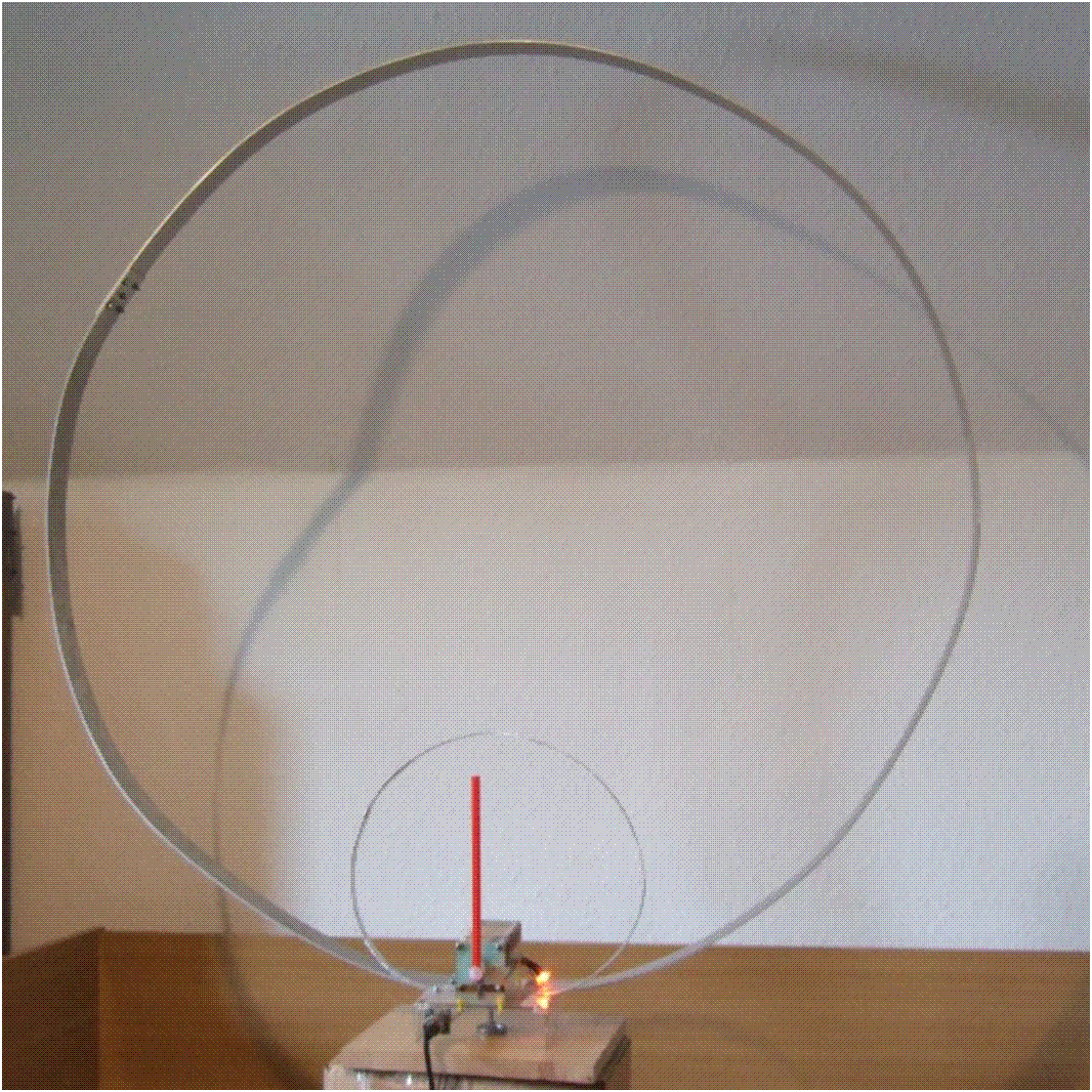
For QRP operation with limited space, a compact and lightweight 'magnetic' loop antenna was built. For the first design (which leaves room for improvement), a long thin piece of aluminium sheet was used (3.14 meters total circumfence, 50 mm wide, 2 mm thickness)
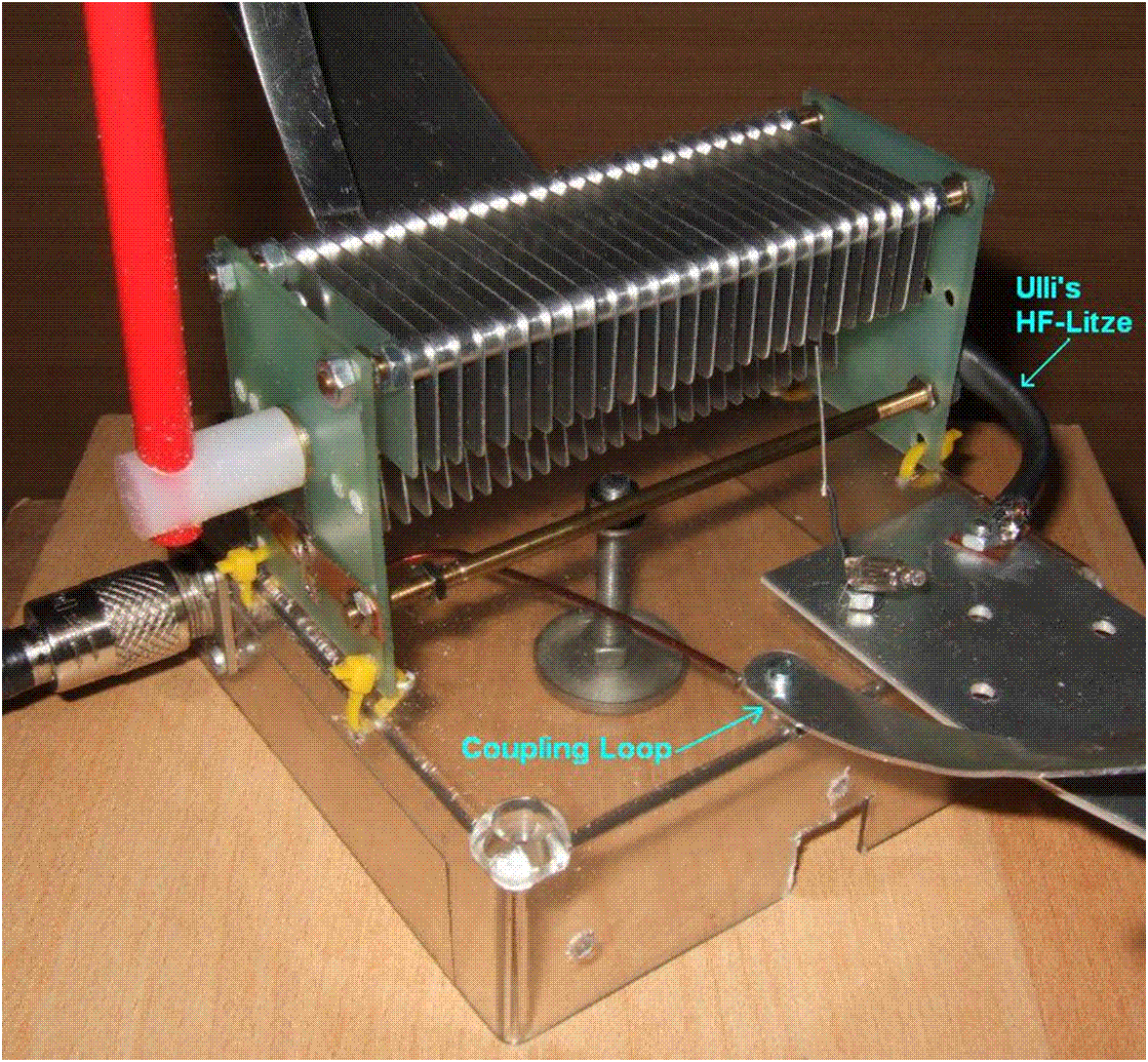
Unlike most classic loop designs, the tuning capacitor and the smaller coupling loop are both at the base of the antenna. The tuning capacitor with approximately 20 ... 250 pF should be replaced with a 'butterfly'-design, but these are either difficult to find or too expensive, so a 'normal' variable capacitor scrapped from an old antenna tuner was used. With this arrangement, the resonant tuning range was 7 to 21 MHz. With a "better" capacitor (lower minimum capacity), tuning above 21 MHz could be easier.
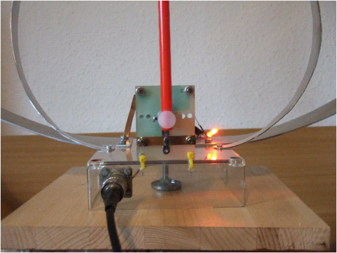
The small neon lamp on the right side of the capacitor initially acted as a tuning aid. One of its legs is connected to the outer loop, the other leg is only capacitively coupled to the other electrode of the tuning capacitor. It later turned out that adjusting the loop for resonance 'by ear' brings the SWR low enough before transmitting (at QRP levels!), the 'fine tuning' should be done with an SWR meter.
The coupling loop's optimum length (circumfence) was found to be 0.6 meters, which is roughly 1/5th of the outer loop's circumfence, which agrees with many other 'magnetic loop recipes' (for example Rothammel's Antenna Book).
Note that unlike other designs, the small coupling loop of this antenna does not touch the larger outer loop ! If it would, the only point where both loops may touch would be the topmost point, which is 'electically neutral' (voltage minimum of the outer loop).
Due to the lack of an electric connection between the loops, there is also no need for a balun !
The plastic 'insulator' at the bottom holds both loops, and the tuning capacitor in place. The entire loop (including insulator) can be rotated on the wooden base, using a single screw visible in the center of the last photograph.
To eliminate the need for a vernier drive, and to stay away from the tuning capacitor, an plastic lever is used to operate it.
Ideas / possible improvements
The electric conductance of the aluminium loop (measured at DC by passing 2 amperes through the loop, and measuring the voltage - 3 mV - across the loop close to its ends) was found larger than it should have been. Calculation:
       sigma = ( Current * Length ) / ( Voltage * Conducting_Area )
   here:
       sigma = ( 2 A  *  3 m ) / ( 0.003 V * 0.002 m * 0.05 m ) = 20 * 10^6 Siemens / meter

     (In Germany, 'sigma' [σ] denotes the electrical conductance.
      In the English literature, 'kappa' [κ] seems more common.)
The electrical conductivity of pure aluminium would be 36.6 Mega-Siemens per meter; and a loop made of pure copper would be even better (sigma = 58 Mega-Siemens per meter).
Since most of the HF current only flows in the outer few micrometers of the conductor, the loop doesn't have to be "solid". A loop made of a long (bent) piece of plastic, carrying a long strip of copper foil (say 70 micrometers thick, and 50 mm wide) would be even lighter than this loop. Experimentation will tell if the reduced loss in the loop is worth the effort, considering the loss in the capacitor. A thin copper loop in combination with a 'butterfly' capacitor, or -even better- a variable vacuum capacitor will help to cut the losses in the loop even further. But at some point losses in the vincinity of the loop (walls, floors, ceilings, eddy currents in metal objects, etc) will dominate, and it possibly doesn't pay off to reduce the losses in the antenna itself.
http://www.qsl.net/dl4yhf/qrp/index.html#indoor_loop
tv tuner for radio receiver
با سلام و عرض ادب
جناب عاملی پدر رادیوآماتوری ایران مطلبی راجع به تبدیل تیونر تلویزیون های قدیمی به گیرنده رادیو در باند وی و یو اچ اف داشتند که با کسب اجازه از ایشون در اینجا مطرح می شود
https://t.me/ep2ma
جناب مهندس پایوندی هم مقاله ای در وبلاگ مهندس فرزاد منتشرکردند که اشاره ای به همین مقوله دارد و توضیح کافی در مورد نحوه انجام این مهم داده اند
http://etesalkootah.blog.ir/1395/10/29/Build_a_50_to_900MHz_Receiver_using_a_TV_Tuner
HF swr meter(new)
با سلام و ارزوی سلامتی و موفقیت همه دوستان رادیوآماتور بمناسبت روز جهانی رادیو
در مجله الکتور ژانویه1980 مطلبی بود که برایم جالب بود در یک مدار برگشت سنج از یک پل نمونه گیر با هسته توروئید استفاده کرده بود و لذا حساسیت را در اچ اف بحد میلی وات رسانده و خیلی خوب شده بود
اصل مطلب مجله جهت اطلاع علاقمندان ضمیمه می گردد


متن کامل مجله در ادامه مطلب
سومین اردوی رادیوآماتوری ایران
با سلام و تبریک یوم الله 22 بهمن و ایام فجرانقلاب اسلامی
دوستان کلوب البرز با راه اندازی ایستگاه خود موفق به شروع تماس و کار کرده و آرزوی همه علاقمندان رادیوآماتوری توفیق روز افزون و موفقیت این دوستان می باشد


HF swr meter
با سلام و تبریک ایام
Barry Zarucki M0DGQ مدار قدرت سنج و برگشت سنجی را برای باند اچ اف طراحی کرده اند که از 10 تا یک کیلو وات را اندازه گیری می کند برای رنج 200 وات از دو عدد توروئیدFT50-43 استفاده شده و برای رنج یک کیلو وات از 6 عدد توروئیدFT114-43
مدار ساده است و توضیحات عکس ها کامل است در صورت علاقه ادرس مطلب نیز درج می شود:
http://www.m0dgq.co.uk/HF%20swr%20meter.html
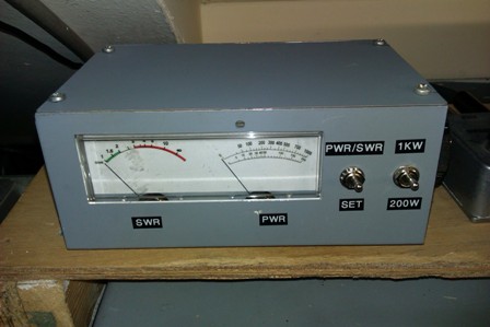
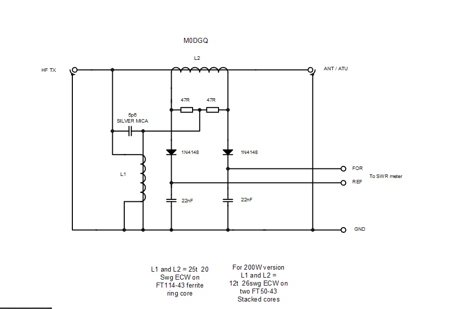
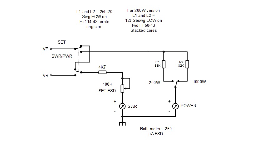
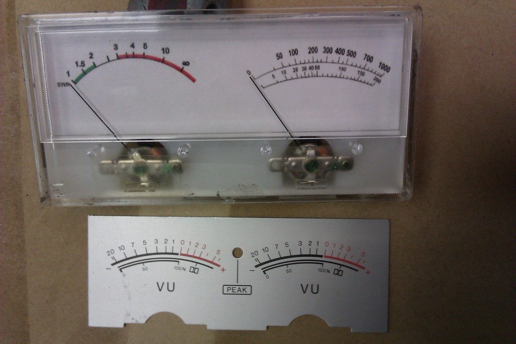
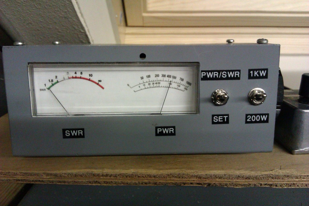
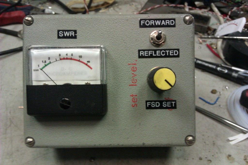
Calibration was done with a Bird meter for comparison, however a diode probe can be used with a DVM using the formula P = Vrms X Vrms / Rload. In other words power in Watts into a 50 Ohm dummy load = Vrms squared divided by 50. The values for resistors R1 and R2 were found by initially using a 100K trimmer and adjusting for correct power reading during calibration, these were then substituted by fixed resistors.
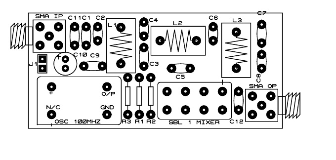
up converter
با سلام و ابراز همدردی و تسلیت بمناسبت شهادت عزیزان آتش نشان در حادثه ساختمان پلاسکو سابق
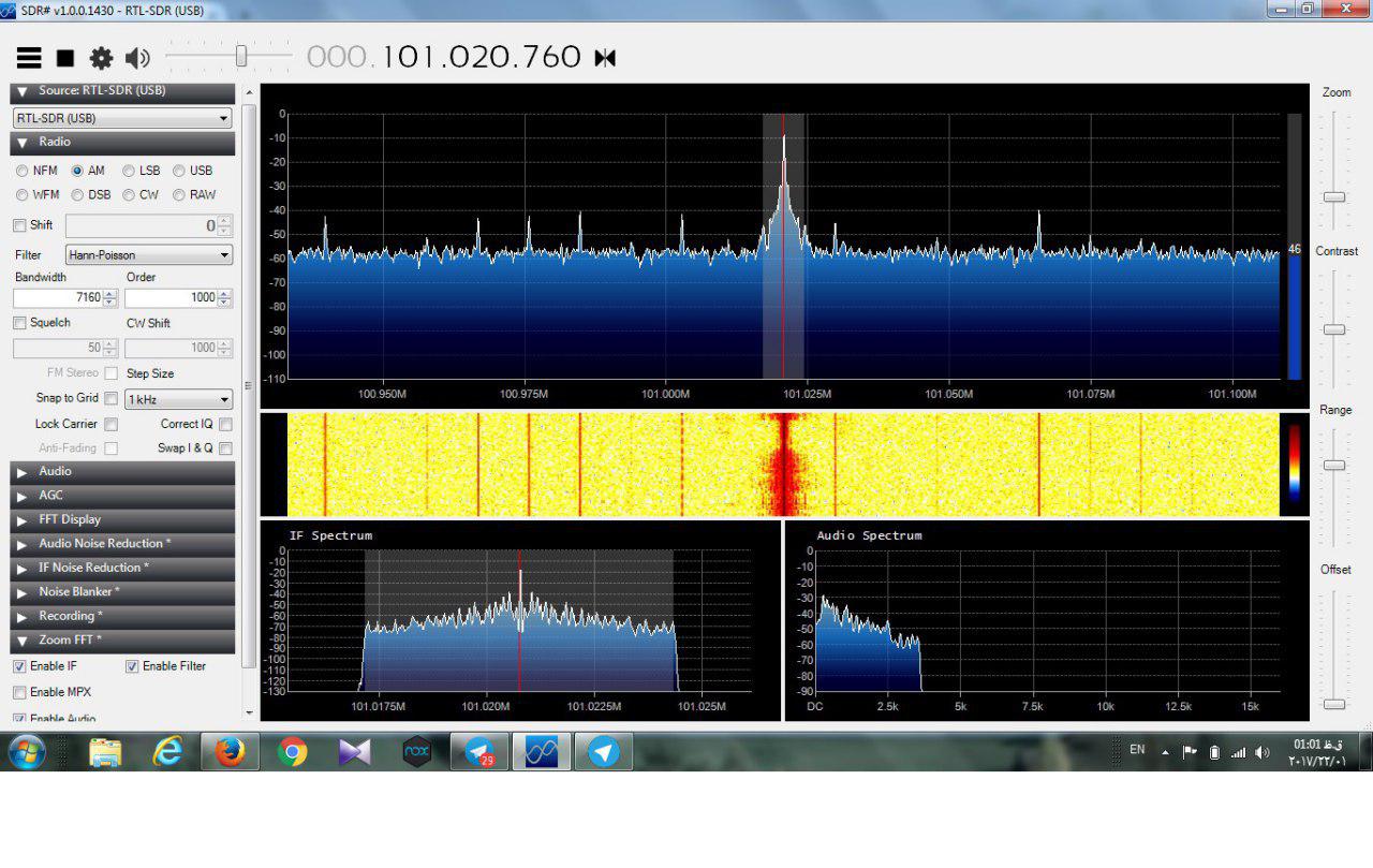
یکی از دوستان در جمع رادیو اماتوری توانستند اپ کانورتری برای باند اچ اف بسازند که امواج کمتر از صد مگا را با اس دی ار خودشان که برای وی اچ اف و یو اچ اف بود بگیرد
کار جالب و قابل تاملی است و خدمتشان خسته نباشید و خداقوت می گویم جناب مهندس احمد ابکه EP4AAA
.jpg)
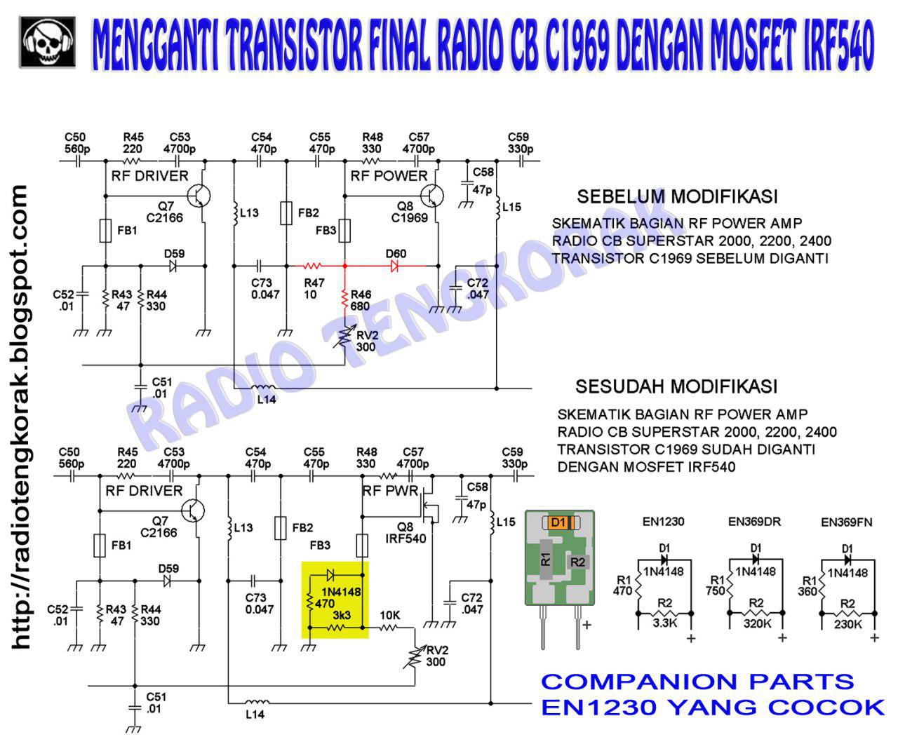
27Mhz amp changing power transistor
با سلام
در تقویت کننده خروجی رادیوهای CB با توجه به تولید نشدن ترانزیستورهای قدرت و کمیاب و گرانی انها این پیشنهاد قابل توجه و بررسی است
شما هم می توانید یک لیزر گازی بسازید برگرفته از سایت etesalkootah.blog.ir
با سلام
شما هم می توانید یک لیزر گازی بسازید
برگزاری کمپ رادیو آماتوری ۳ روزه در شمال کشور
http://irandx.ir/?p=302
با توجه به درخواست برگزاری کمپ رادیو آماتوری ۳ روزه در شمال کشور شهرستان نور که ماه گذشته به سازمان تنظیم مقررات و ارتباطات رادیویی تسلیم شده بود ، امروز مجوز این برنامه بدستمان رسید که از این طریق خدمتتون اعلام میکنم
مجوز برنامه برای ۲۰، ۲۱ و ۲۲ بهمن ماه گرفته شده
دوستانی که علاقه مند به حضور در این برنامه هستند تا پایان دی ماه فرصت دارند اعلام حضور نمایند.
تماس با ادمین
@smazimi
لینک عضویت در کانال گروه رادیویی البرز
@alborzdx
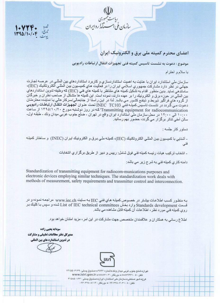
تاسیس کمیته فنی INEC TC 103
بحرالعلوم دبی, [۲۵.۱۲.۱۶ ۱۲:۱۷]
اعضای محترم گروه رادیوآماتوری
با سلام و احترام
ضمن دعوت از سرکارعالی/جنابعالی جهت حضور در نشست تاسیس کمیته فنی INEC TC 103 ، خواهشمند است در صورت مرتبط بودن دامنه کاری به سایر صاحبنظران معرف حضور اطلاع رسانی فرمایید.
با سپاس
حمیدرضا دامغانی
دبیر کمیته TC 100
اعضای محترم گروه رادیوآماتوری
با سلام و احترام
به استحضار می رساند کمیته فنی INEC TC 100 و INEC TC 110 با عنوان های " تجهیزات و سیستم های صوتی، تصویری و چندرسانه ای " و " وسایل نمایشگر الکترونیکی" متناظر با کمیته فنی IEC TC 100 و IEC TC 110 در دی ماه سال 94 تاسیس شد و آغاز به فعالیت نموده است. جهت عضویت و مشارکت در این کمیته فنی به صفحه ویژه کمیته جهت پر نمودن فرم های عضویت مراجعه فرمایید.
با سپاس
حمیدرضا دامغانی
دبیرخانه های کمیته فنی 110 وINEC TC 100
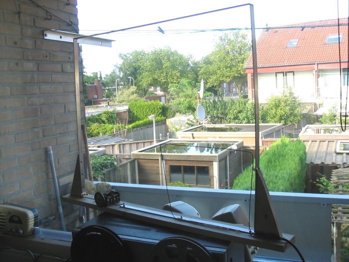
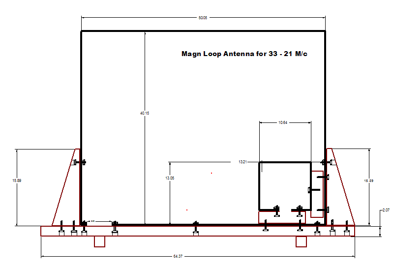
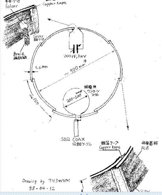
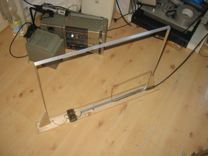
انتن لوپ
با سلام
انتن لوپ قابل استفاده در بالکن و داخل فضای محدود
http://members.home.nl/radiomorningstar/loop.htm
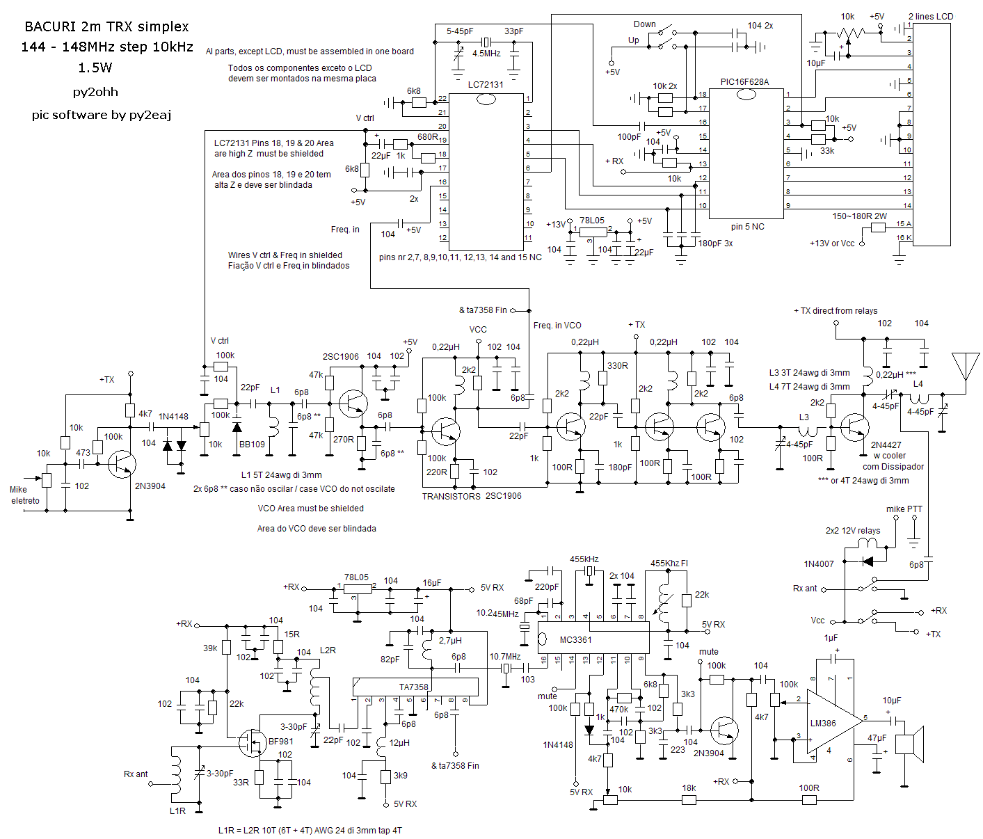
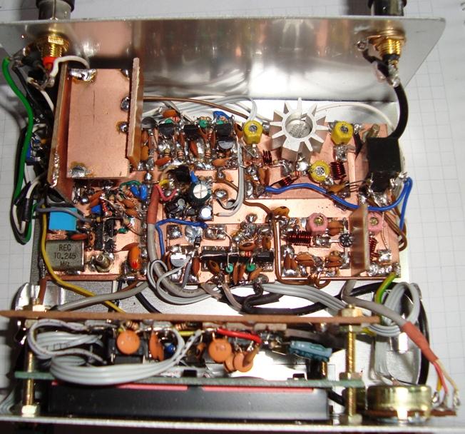
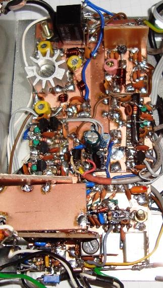
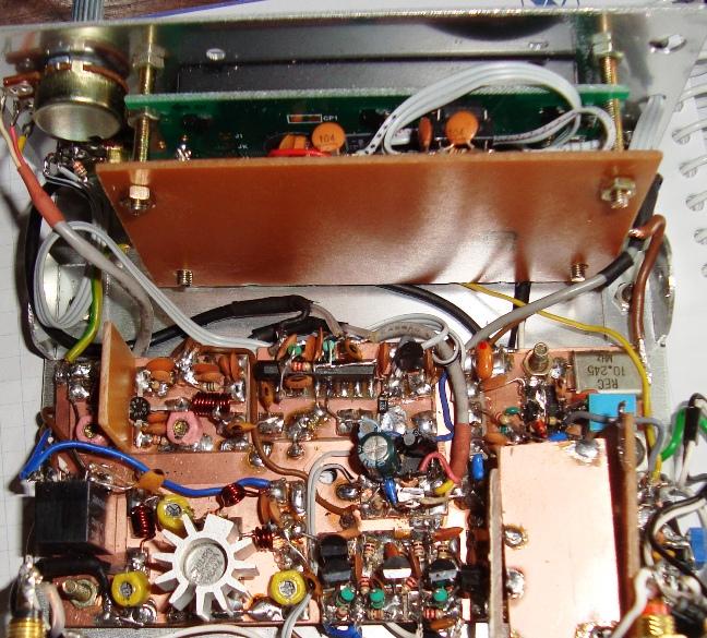
144Mhz radio
video : http://www.youtube.com/watch?v=8SofWPlKgPw
با سلام و تبریک هفته وحدت و میلاد مسعود رسول رحمت
2SC2999 150mw 750mhz 30ma
2SC2786 600mhz 250mw 20ma
2SC1923 550mhz 100mw 20ma
2SC1674 600mhz 250mw 20ma
2N2369 metalico pulso 0,68w 200ma 500mhz
BF224 600mhz 1w 50ma
BF198 400mhz 25ma 0,5w
BF240 1,1ghz 50ma 350mw
BFW16 1,2 ghz 1,5w 150ma rf catv ==>PA
BFY90
2SC2926 50ma 300mw 750mhz
73 de py2ohh miguel
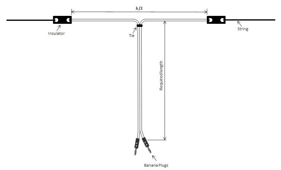
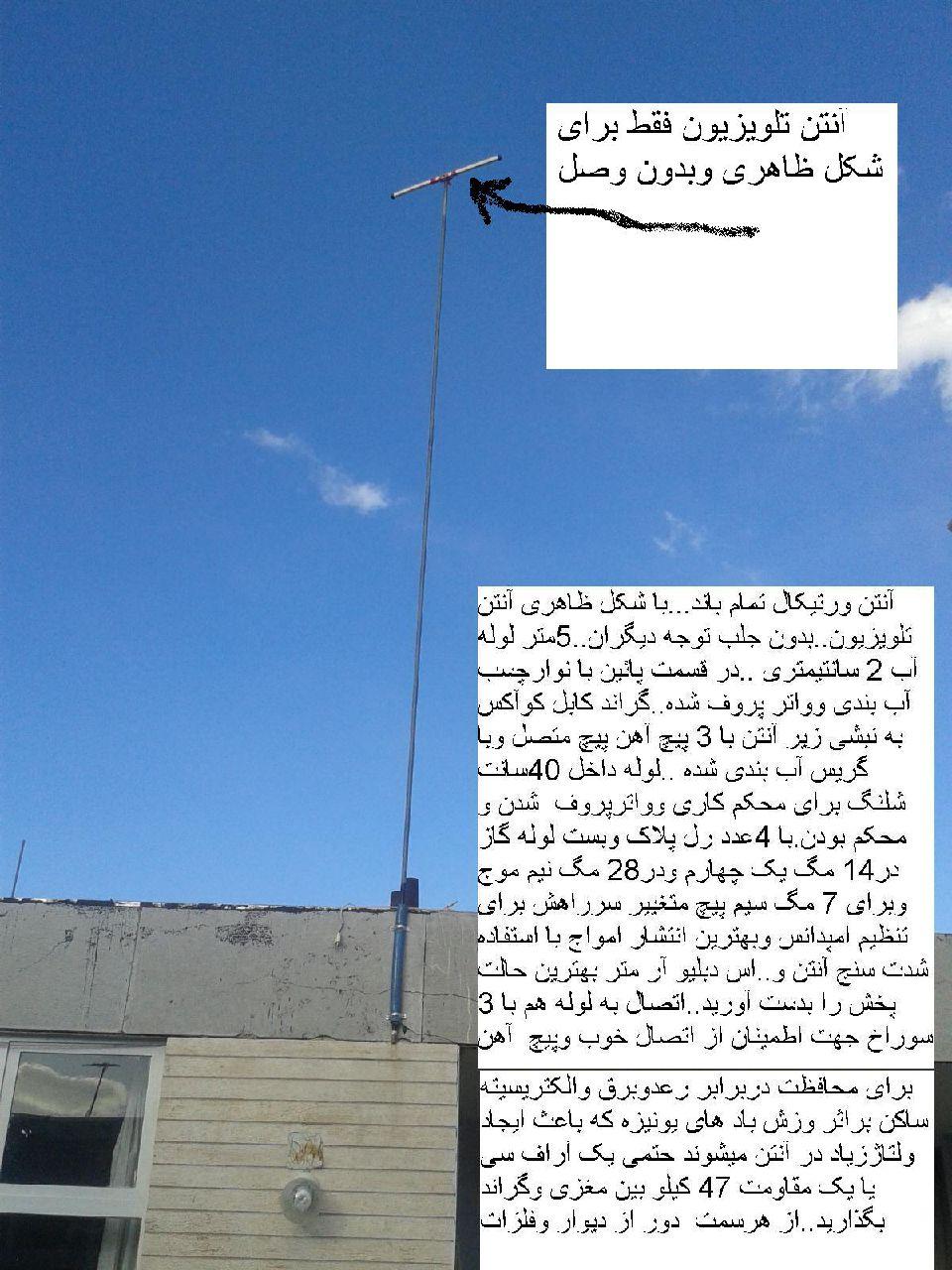
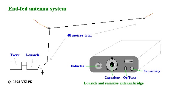
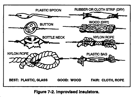
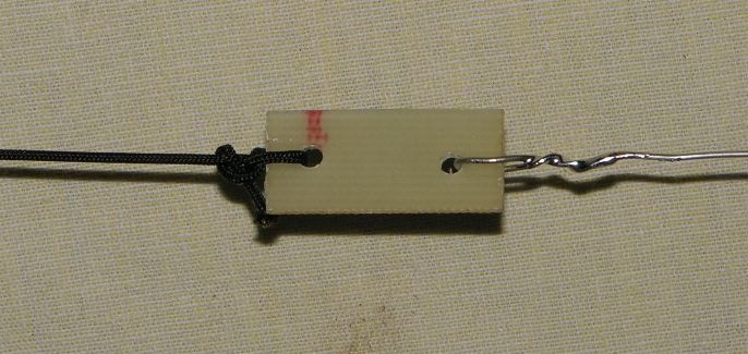
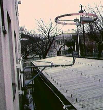
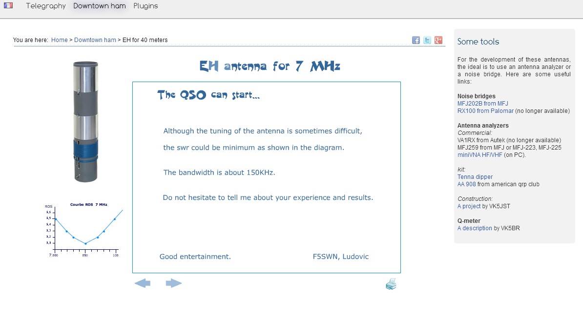
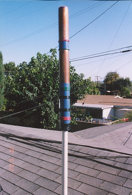
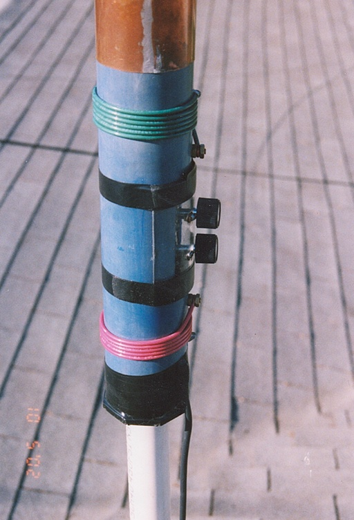
آنتن برای 14 مگا
با سلام و آرزوی سلامتی و موفقیت روز افزون دوستان
انتن برای باند 20 متر یا 14 مگا بروش ساده تشکیل شده از :
multi band radio
با سلام
اخیرا دوستان طرح تقویت کننده ای را معرفی کردند که بسیار جالب و کارامد بود و دوستم مهندس دل قوی اصل انرا پیدا کرده و در اختیار دوستان عزیز قرار دادند
http://www.4qdtec.com/mostest.html
A better test
What the test above actually measures is the pinch-off voltage: the highest voltage that can be put on the MOSFET's gate without it starting to conduct. The circuit below shows a better way.

There are two push switches, one is a changeover switch, the second is a push to make (normally open). I use a couple of microswitches. It uses the diode test of a multimeter, or you could use any power supply, or a 9v battery, with a resistor in series with the MOSFET to limit the current.
With both switches in the normal position, the capacitor C1 charges up to the open circuit voltage of the diode tester. The capacitor's value is not critical, 10n-100n is fine. When Sw1 is pushed, the charged capacitor is disconnected from the meter leads and reconnected to the MOSFET gate. The MOSFET should turn fully on, so the diode tester will indicate a short circuit.
Release Sw1. The MOSFETs gate is still charged. Only leakage will discharge it, so the MOSFET should still stay conducting for quite some time.
Push SW2 to short the MOSFETs gate to source, to discharge it. The meter should show an open-circuit.
Alternatively, connect the capacitor to meter +ve via a diode, to allow the capacitor to charge, Now when the capacitor is connected to the gate, the MOSFET will conduct but the diode will stop the conducting MOSFET from discharging the capacitor.
Meter Check of a Transistor (JFET)
http://www.allaboutcircuits.com/textbook/semiconductors/chpt-5/meter-check-transistor-jfet/
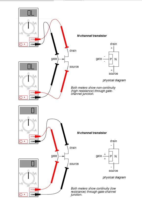
Testing a JFET with a multimeter might seem to be a relatively easy task, seeing as how it has only one PN junction to test: either measured between gate and source, or between gate and drain.
Testing continuity through the drain-source channel is another matter, though. Remember from the last section how a stored charge across the capacitance of the gate-channel PN junction could hold the JFET in a pinched-off state without any external voltage being applied across it? This can occur even when you’re holding the JFET in your hand to test it! Consequently, any meter reading of continuity through that channel will be unpredictable, since you don’t necessarily know if a charge is being stored by the gate-channel junction. Of course, if you know beforehand which terminals on the device are the gate, source, and drain, you may connect a jumper wire between gate and source to eliminate any stored charge and then proceed to test source-drain continuity with no problem. However, if you don’t know which terminals are which, the unpredictability of the source-drain connection may confuse your determination of terminal identity.
A good strategy to follow when testing a JFET is to insert the pins of the transistor into anti-static foam (the material used to ship and store static-sensitive electronic components) just prior to testing. The conductivity of the foam will make a resistive connection between all terminals of the transistor when it is inserted. This connection will ensure that all residual voltage built up across the gate-channel PN junction will be neutralized, thus “opening up” the channel for an accurate meter test of source-to-drain continuity.
Since the JFET channel is a single, uninterrupted piece of semiconductor material, there is usually no difference between the source and drain terminals. A resistance check from source to drain should yield the same value as a check from drain to source. This resistance should be relatively low (a few hundred ohms at most) when the gate-source PN junction voltage is zero. By applying a reverse-bias voltage between gate and source, pinch-off of the channel should be apparent by an increased resistance reading on the meter.
فرستنده لامپی
با سلام و تسلیت ایام شهادت سرور آزادگان جهان حسین ابن علی علیه السلام
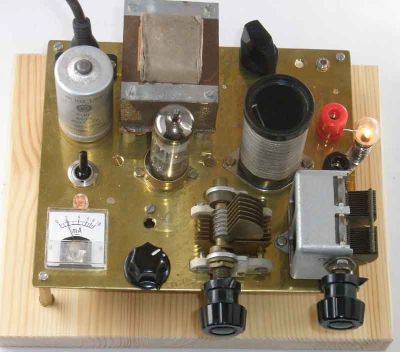
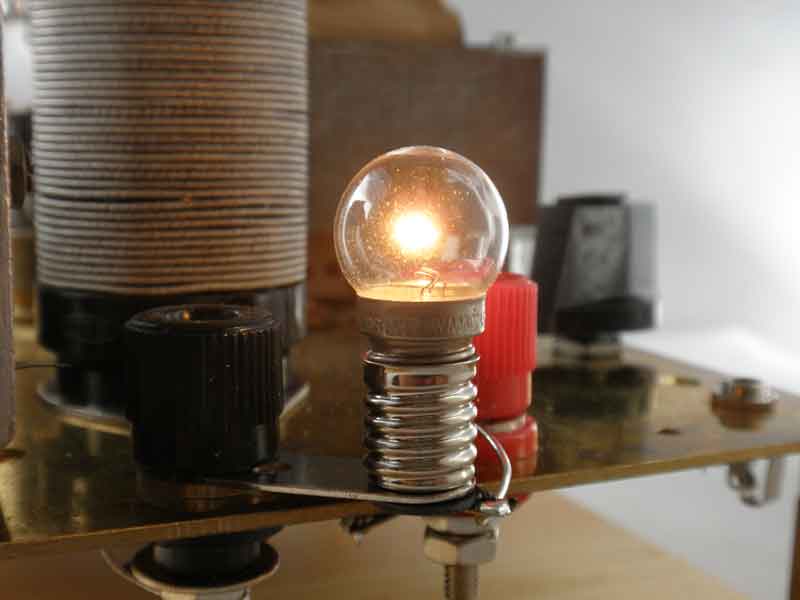
مدار فرستنده لامپی ساده ای بدستم رسید جهت اطلاع عزیزان تقدیم می گردد
http://www.sm7ucz.se/AM_Transmitter/AM_transmitter.htm
ECL85 medium wave AM-Transmitter
Men det kunde lika gärna ha varit ECL80, ECL82, ECL84 eller ECL86
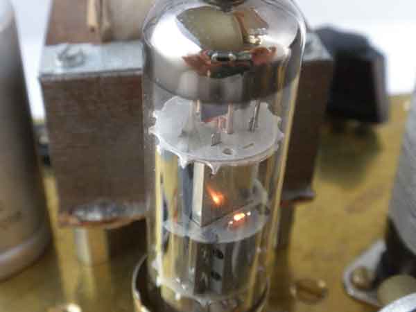
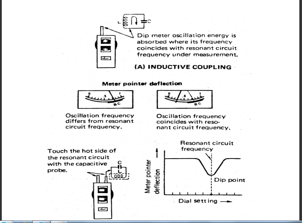
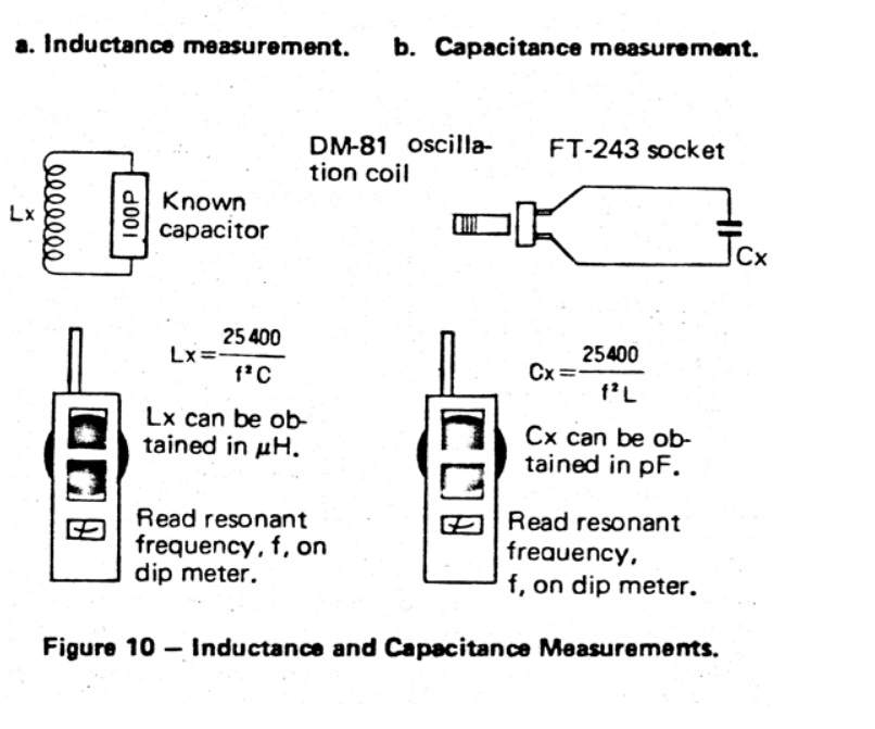
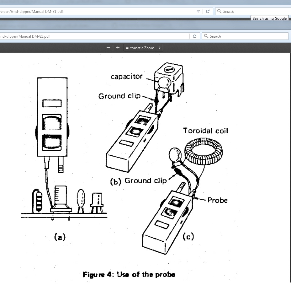
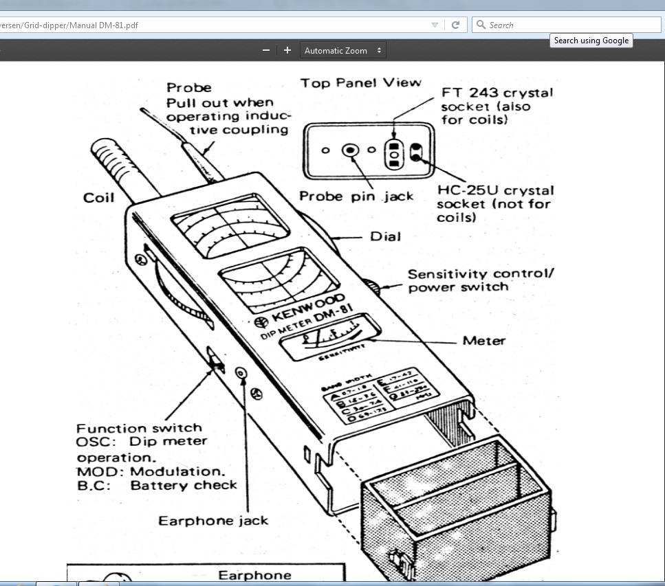
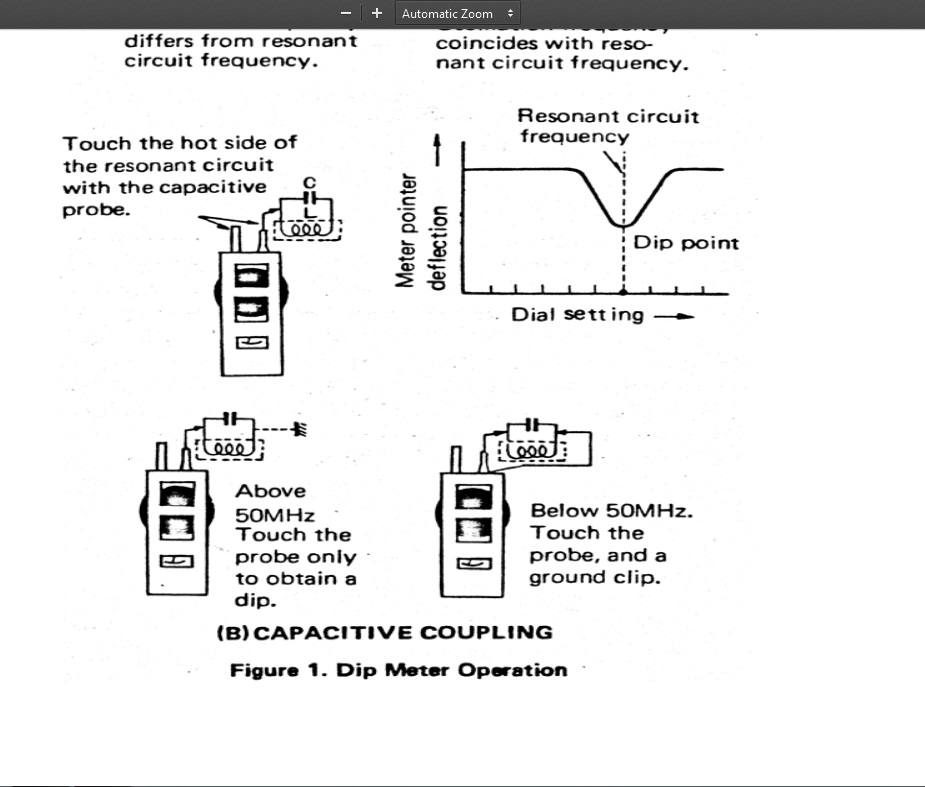
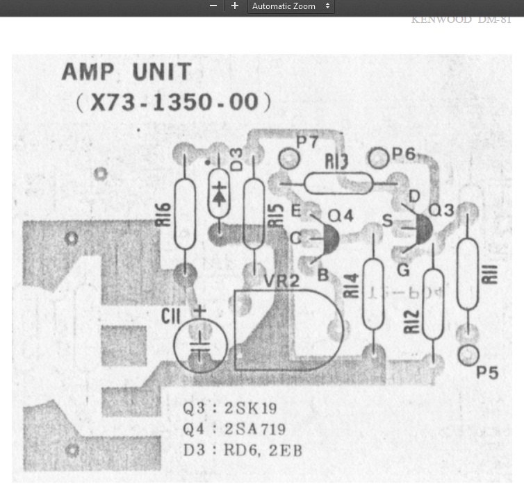
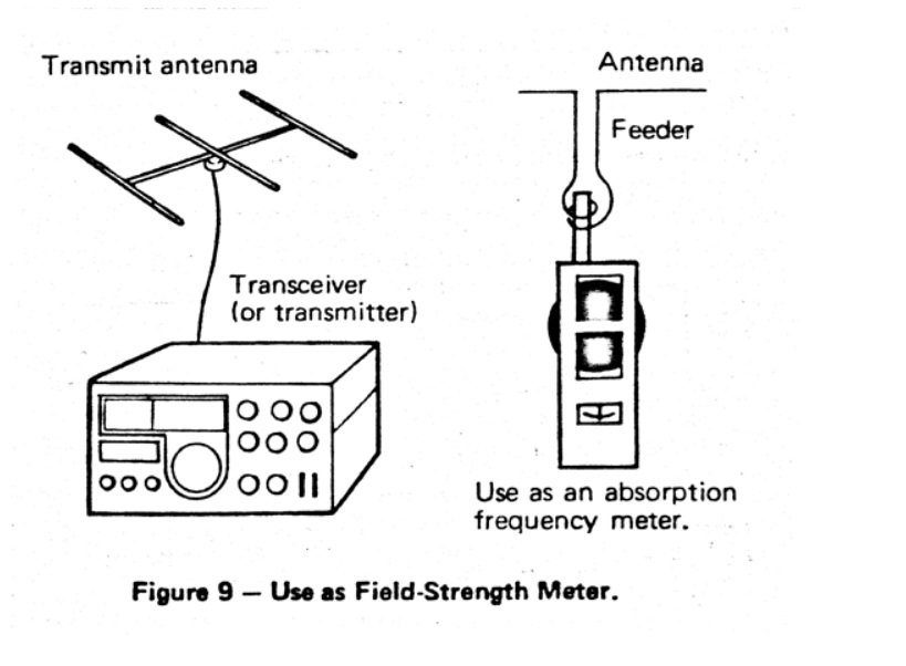
Grid dip meter
با سلام و تسلیت ایام شهادت سرور آزادگان جهان حسین ابن علی علیه السلام
یکی از ابزار لازم کارگاه رادیو آماتور دیپ متر می باشد که توضیحی چند به عرض می رسد


ادامه مطلب در ادامه مطلب
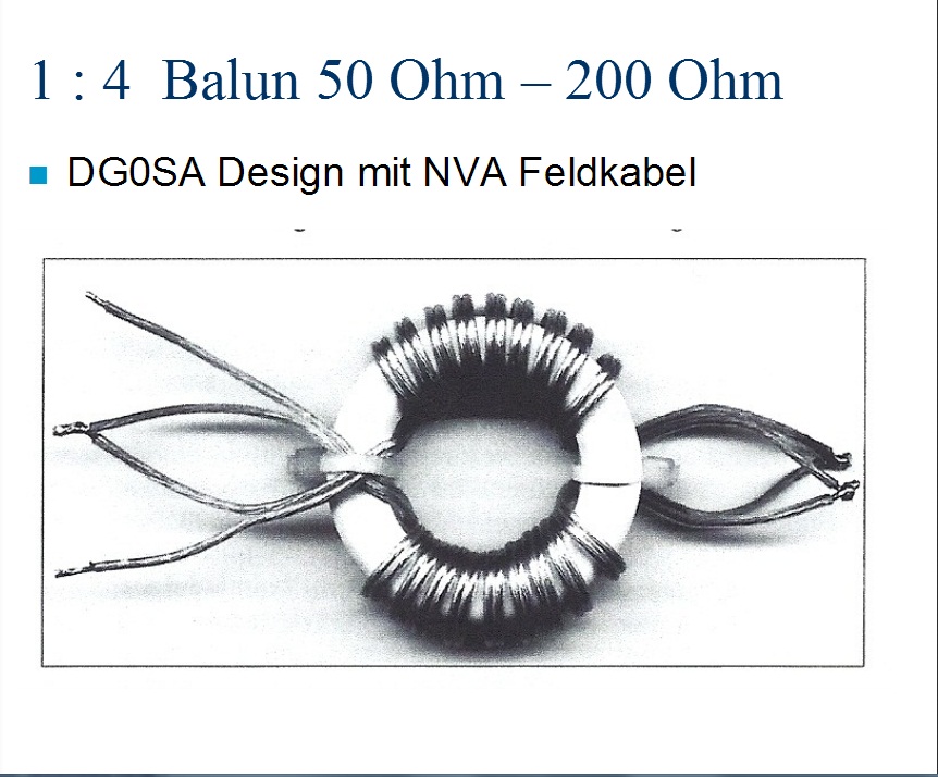
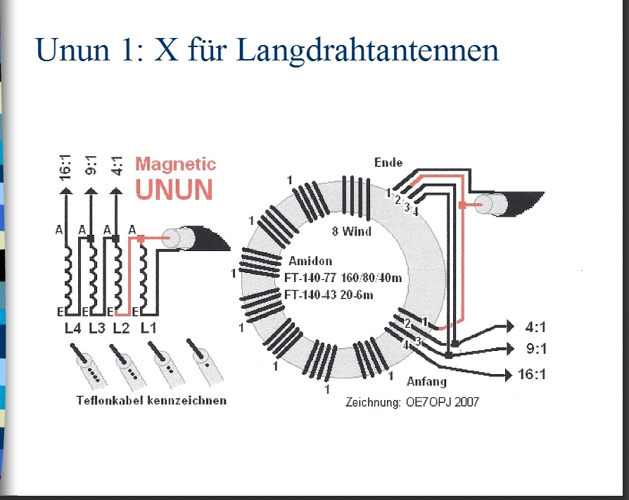
Maching Baloon
با سلام
http://www.darc.de/fileadmin/_migrated/content_uploads/Baluns__Ununs___Co_01.pdf


تغییر ترانزیستور 1969 تقویت قدرت رادیو به IRF510
با سلام و درود فراوان و تشکر بسیار از دوست و سرور عزیزم جناب مهندس فرشچی
مطلب فوق را ایشان در گروه رادیو آماتورها آورده بودند که بدلیل جالب بودن اینجا اراعه می شود
CW-SSB-transceiver direct conversion to 10 meters
http://www.diagram.com.ua/list/rst-kb0.shtml
For SSB transceiver and CW transmitting and receiving in the range 28 ... 29.7 MHz. The device is built by direct conversion circuit with a common mixer - a modulator for receiving and for transmitting.
Specifications transceivers:
1. The sensitivity in reception mode for the signal / noise ratio of 10 dB, not worse ........ 1 mV.
2. The dynamic range of the receiving path, as measured by the method dvuhsignapnomu about .... 80 dB
3. Receiving channel bandwidth at -3 dB .................................... 2700Gts.
4. Bandwidth unipolar radiation transmission ....................... 2700 Hz
5. The carrier frequency and the non-operating side band suppressed not worse than ............................. 40 dB
6. The transmitter output power in CW on 750m load ............................... 7 W
7. Disposed frequency oscillator 30 minutes after the warm-up not exceeding ........ 200 Hz / hr.
Schematic diagram of the transceiver (without telegraph node) is shown in Figure 1. The transceiver has separate receiving and for transmitting high-frequency and low-frequency paths common to both modes is the mixer-oscillator and modulator VFO
Fig.1
Variable Frequency Generator (GPA) is made of two field-effect transistors and VT5 VT6 connection with a source driver. It operates at a frequency equal to half the frequency of the received or transmitted signal. When working at the reception and the transmission of the output circuits of the GPA is not switched, and does not change the load on the GPA. As a result, the transition from reception to transmission or vice versa, the frequency of the GPA is not rejected. Setting is made within a range by means of alternating air dielectric capacitor C10, which is part of the VFO loop. The SSB transmit mode, the microphone signal is amplified by the operational amplifier A2 and fed on to faeovraschatel elements L10, L11, C13, C14, R6, R7, which in the frequency range 300 ... 3000 Hz provides a phase shift of 90 °. The circuit L4 C5 serving total load mixers diodes VD1-VD8, allocated signal in the upper sideband range 28-29,7 MHz. High broadband faeovraschatel L8 R5 C9 in this range provides a phase shift of 90 °. Dedicated single-sideband signal through a capacitor C6 is supplied to a three-stage power amplifier transistors VT7-VT9.
Cascade pre-amplification and isolation of the mixer-modulator output circuit is formed on the transistor VT9. The high input resistance combined with low capacitance C6 provides a minimal impact on the power amplifier circuit.
In VT9 collector circuit switched circuit tuned at mid-range. The intermediate stage FET VT8 works in Class mode, "B", and the output stage in Class mode "C".
"U" -shaped low-pass filter on the L12 C25 and C26 clears the output signal from the high-frequency harmonics and ensures coordination of the output impedance of the output stage with impedance of the antenna. PA1 ammeter is used to measure current output transistor drain and indicates the correct settings "P" -filter.
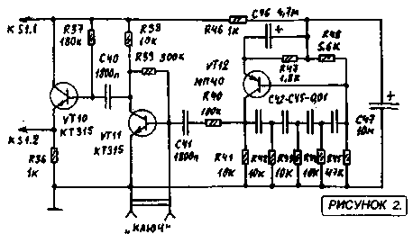
Wire mode is provided by replacing the A2 amplifier sine wave oscillator frequency of 600 Hz (see Figure 2). Switching CW-SSB is done with S1. Telegraph key controls displacement VT11 preamp generator, and thus feed the low-frequency signal to the modulator.
CW-SSB-transceiver direct conversion to 10 meters
In receive mode, the power of the transmitter 42 on the stage is not supplied and the power amplifier and microphone amplifier are disabled. At this time, 12V voltage is applied to the cascade receive path.
The signal from the antenna is supplied to the input circuit L1 L2 C3 through the coupling coil, she agreed with the resistance of the circuit impedance of the antenna. On VT1 transistor RF amplifier made. The gain stage is determined by the bias voltage at its second gate (divider resistors R1 and R2). The load stage is L4C5 circuit connection RF amplifier stage with this circuit is carried out by means of the coil L3 Communications. With regard coil L5 signal is sent to a demodulator diode diodes VD1-VD8. The coils L8, L9 and L10 and the phase shifter is isolated L11 AF signal in the frequency band 300 ... 3000 Hz, which, via a capacitor C15 to the input of the operational amplifier A1. Strengthening of this circuit is determined by the sensitivity of the main transceiver in receive mode. The following AF amplifier transistor VT2-VT4, whose output signal is sent to the AF compact speaker volume B1 reception is controlled by the variable resistor R15.
In order to avoid loud clicks when switching modes "RX-TX" on UMZCH power transistor VT2-VT4 is served both in reception and transmission.
Most of the details of the transceiver is mounted on three printed circuit boards, pictures of which are shown in Figures 3-5. In the first board arranged the details of the input RF amplifier receiving channel (transistor VT1), the mixer parts - fazovraschayuschimi modulator circuits, as well as details of the local oscillator. The second board - low-frequency cascades on chips A1 and A2 and transistor VT2-VT4. on the third board amplifier power transmission path is placed. The board with mixer-modulator, RF amplifier and the GPA is screened.
Chassis transceiver has a width of 350 mm and a depth of 310 mm. On the front cover removed all controls and sockets for microphone and telegraph key. The speaker is also installed on the front panel, it is screwed M3 screws through the rubber grommets Mode Switching "RX-TX" is made pedal that -Includes disables voltage 42 V and operates two electromagnetic relays, one of which switches the antenna and the second voltage is 12 V at the receiving tract. Relay coil voltage feed 42, and de-energized include reception mode (RX).
Sockets for connecting the antenna, the pedals and the source 12 are located on the rear panel.
For the transceiver power used by the base stationary power supply unit, which supplies a constant stabilized voltage of 12 V with a current of 200 mA and a constant voltage of 42 V unstabilized with currents up to 1 A.
The transceiver used fixed resistors MLT on the power indicated in the diagrams.
Trimmer SDR-4a. Contour Ceramic capacitors necessarily, Trimmers CPC-M. Electrolytic capacitors K50-35 type or similar import. Variable capacitors oscillator and output circuits - with air dielectric.
For the winding contour coils RF amplifier, mixer and the transmitter using ceramic scaffolds 9 mm with cores trimmers SCR-1 (can be plastic frames from the paths UPCHI old tube TVs, but their thermal stability is much worse than that of the ceramic). Low-frequency coil mixer -modulyatora L8 and L9 are wound on the ring core of ferrite K16h8hb 100NN or more high-frequency (100VCH, 50VCH). The coils L10 and L11 are wound on the carcasses of the OB-30 2000IM1 ferrite. On these cores wound coil generators and erase bias semiconductor reel tape recorders.
Transistors KP303G KP303 can be replaced with any letter index or KP302. The transistor can be replaced by KP350A KP350B, KP350V or KP306. The transistor KP325 - by KT3102. Powerful FETs KP901 and KP902 can be any letter indices. For UMZCH fit any silicon and germanium (respectively) transistors corresponding structure. KD503 diodes can be replaced by KD514, adiod D9 to D18.
Establishing transceiver begin with GPA By adjusting core L7 and the inclusion of additional capacitor (5-30 pF) in parallel C10 generator is necessary to achieve the overlap in frequency 14.0 ... 14.85 MHz.
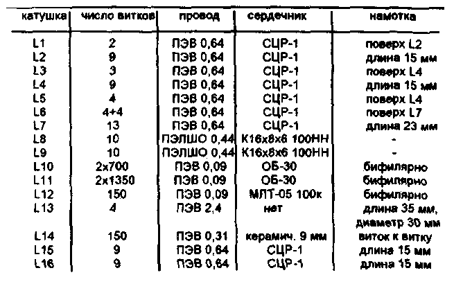
Table 1
CW-SSB-transceiver direct conversion to 10 meters
The work of the local oscillator can be checked using the RF frequency and RF voltmeter the voltage at each of the L6 coil halves should be 1.6 ... 1.8 V. If it is not included in these limits - you need to choose the number of coils L6. Now you need to go to the setup microphone amplifier and mixer - modulator. Do not connect the power 42 to apply 12V voltage at the output 7 A2 and test the functionality of the amplifier. Adjust the sensitivity can be the selection of the nominal value R31.
To set the mixer - the modulator need an oscilloscope, millivolt and tone generator (GZCH). With millivoltmeter and adjust the generator L11 contour C 14 on the frequency of 480 Hz, then loop L10 C13 on the frequency of 1880 Hz. Log phase shifter is disconnected from the capacitor C1S and C41, and the outputs from the L8 and L9 coils. Sign "X" and the oscilloscope AF generator output is connected to a connection point L10 and L11 coils. By the oscilloscope input "V connect SI L10 junction with the generator signal is fed to a frequency of 480 Hz In the oscilloscope display should be straight line sloping If instead the ellipse -... You need to fine tune the loop L11 S14.Zatem to input" Y "connected connection point L11 C12 and, in the same way check setting L10 C13 to the frequency of 1880 Hz. Thereafter, to the input of the oscilloscope "X" instead of the input of the phase shifter are connected free of its output. The channels of the oscilloscope sets the same gain. GZCH tuned to the frequency of 1880 Hz. The resistors R6 and R7 temporarily replace variable to 1 kW. Turn the R6 engine to achieve the appearance of the screen circumference. Then, setting GZCH 480 Hz is chosen in the same way the resistance of the resistor R7.
The setting is correct if the frequency change of the output GZCH in the range of 300 ... 3000 Hz on the oscilloscope screen, a circle will continue.
Resistor R5 achieve the best possible suppression of the lower sideband.
input circuit setting and L4C5 circuit to produce high frequency range. Then, sequentially energizing the power amplifier stages set up in the middle of the circuits L16 and L15 C34 C32 range. Setting the output stage is performed in the equivalent antenna connected - resistor 75 Ohm 10 W (you can solder the battery of four parallel connected resistors 2W 300 Ohm each).
Setting UMZCH comes to setting the selection of resistor R16 to the emitter voltage VT3 and VT4 equal to half the supply voltage.
Author: Bortko B .; Publication: N. Bolshakov, rf.atnn.ru
سایت دانلود رایگان
با سلام
ادرس ذیل سایت بسیار مناسب رایگان جهت در یافت نقشه و اطلاعات اکثر وسایل الکترونیکی منجمله فرستنده گیرنده ها و مجلات و کتب می باشد
http://www.diagram.com.ua/english/library/funkamateur-magazine/funkamateur-magazine.php?row=1
http://www.diagram.com.ua/library/elektronika-usiliteli/elektronika-usiliteli.php?row=1
http://www.diagram.com.ua/english/library/handbooks-rcomp-motorola/

ورود کاربران

عضويت سريع

پشتيباني آنلاين

آمار

خبرنامه

آخرین نطرات کاربران
 جواد یاور مطلق - درود
 بلا بدور باشه مهندس !
انشالله همیشه سرحال سالم تندرست باشید !
پاسخ:با درود و سپاس از لطف شما دوست گرامی بدرود - 1403/1/29
 یک هم وطن - من بدون مدار این رادیو ساختم باصدای واضح و بلند بدون برق و باطری
 پاسخ:باتشکر از لطفتان امیدوارم بقیه دوستان هم همت کنند و دست به اچار و هویه شده خودشان بسازند و لذت ساختن را ببرند چون در داشتن لذت نیست هنر ساختن است - 1402/6/13
 AEC - درود
استاد ممنون خیلی خوب و عالی
پاسخ:باسلام و تشکر از لطف و مرحمت شما دوست عزیز و گرامی - 1400/8/28
 پرویز مهرزاد - سلام ودرود استاد عبدالحق عزیز بسیار خوشحالم که سایت جنابعالی بامطالب جدید وعالی دوباره فعلیتش را شروع نموده است.
پاسخ:با سلام تذکر بجا و بموقعی بود بسیار متشکرم - 1400/8/28
 ایزدی - یه مشکلی داره این طرح. کل سلف ها با هم 12. 7 میکرو میشه که با خازن 270 پیکو، فرکانس مرکزی فیلتر 2.7 مگا هرتز می شه. کمترین سلف هم (0.1 میکرو) با همون خازن 270 پیکو 30 مگاهرتز رو رد می کنه. بنا بر این نیازی به خازن های دیگه نیست. دوستان دیگه نظرشون چیه.
پاسخ:باسلام و تشکر کل خازن ها و سلفها برای فرکانس 1800کیلو که ابتدای باند رادیو اماتوری است کم است و بسختی تنظیم می شود اما برای 3500 بله زیاد است - 1399/8/24
 هومن - سلام .علت استقبال نکردن در خور توجه همین نا واردیست .این مطلب بسیار گنگ و پر از اشتباه هست
 پاسخ: سلام بنده هم ضمن تائید نظر شما درخواست می کنم مطلب کامل تر و بهتر و درست تر را بفرمائید بنده بنام خودتان درج و منتشر نمایم
پاسخ:https://t.me/joinchat/AAAAAEJj30AwLGIyi_UQ3g مدارات لامپی - 1396/12/17
 علی - سلام شما مکتبی و انقلابی هستید درسته ؟
پاسخ: سلام بهیچ عنوان و تقریبا هیچ جائی من چنین ادعائی نکرده ام اما این همه شهید و زخمی و جانباز و اسیر و زحمت و فعالیت برای حفظ انقلاب و سرزمین عزیزمان ایران خیلی حرام لقه گی و بی اصل و نصبی می خواهد که چشم خودرا ببندیم و از این اب و خاک حمایت و به این مردم عشق نورزیم حالا شما اسم انرا هرچه دوست دارید بگذارید نظرتان محترم است - 1396/12/17
 هومن - سلام
 بنده یکی از علاقمندان لامپ هستم . و 10 سال اخیر را بر روی مدارات لامپی کار کردم .با سرچ اینجا را پیدا کردم .می خواستم ببینم در زمینه مخابرات فعالیت لامپی در ایران هست ؟
این مطلب راجب لامپ واقعا توجه مخاطب علاقمند را جلب می کند ؟
من فکر می کنم نویسنده اصلا راجب لامپ حس خوبی ندارد .عذر خواهی می کنم
پاسخ:سلام دوست عزیز از صراحت و فصاحت بیان شما خوشحالم مطلبتان راجع به نویسنده مطلب لامپ کمی کم لطفی و شاید سخت گیری در بر دارد نویسنده مطلب استاد عاملی بزرگ رادیو اماتوری ایران هستند و مطلب را بی اندازه ساده و اسان گفتند چون اکثر جوانها از لامپ و ولتاژ کار ان وحشت داشته و تقریبا هیچ نمی دانند اما ظاهرا شما در مورد لامپ مطلع و ازموده هستید لذا برخود نگیرید شما هم اگر در مورد لامپ و یا مطالب استاد عاملی نقد و نظری دارید بسیار خوشحال می شوم مکتوب بفرمایید تا در همان بخش یا در بخش جدید بنام خودتان منتشر شود
پاسخ:https://t.me/joinchat/AAAAAEJj30AwLGIyi_UQ3g - 1396/12/16
 سعیدی - سلام استاد بنده بی جواب ماندم
 پاسخ:با سلام و پوزش از تاخیر طبق تجربه دوستان این مدار به دلیل نامرغوب بودن قطعات نو موجود در بازار معمولا در ابتدا کار نمی کند لذا بتوصیه استاد عاملی بهنر است از قطعات اوراقی رادیو و ضبط ها استفاده شود قطعات معمولا در گیر این رادیو ابتدا ای سی سویچ یا کلید زنی است که یک مدل خاصش برای مدار مناسب است و مدلهای دیگر فرکانس کار و ولتاژشان مناسب نیست درمورد ای سی مدولاتور و دمدولاتور 3028 این ای سی هم بشدت مورد شک و شبهه است در موردی باتعویض 5 عدد ای سی دو عدد که بهتر بود در مدار بکار گرفته شد لذا بهترین روش استفاده از مرحله مرحله و گام بگام کار کردن رادیو است ضمن انکه اگر فرستنده کار بیفتد گیرنده هم کار خواهد کرد و بالعکس لذا شما می توانید مدار را از میکروفون در حالت فرستنده یا بلندگو در حالت گیرنده شروع نمایید و اگر مسیر سیگنال جدا باشد در نقشه شما می توانید از تقویت صدا شروع کرده و به دمدولاتور رفته و سپس به فیلتر و بعد میکسر وی اف او و در اخر به فیلتر تنظیم باند بروید و حد اکثر سیگنال و حساسیت را بدست اورید پس فیلتر های رادیویی یا بقول شما توکو ها قسمت اخر تنظیم و تعقیب مدارتان است اگر شد برای اطلاع شما و سایر دوستان مدار را در حالت گیرنده و فرستنده جدا اراعه خواهم داد یا با رنگ مسیر سیگنال را جدا می کنم که راحت تر باشد اگر شما عضو تلگرام هستید در یکی از گروه های رادیو اماتوری بیایید و مستقیما با دوستان سازنده و استفاده کننده رادیو تماس گرفته راهنمایی شوید اگر نه ادرس ایمیلتان را بدهید تا راهنمای مونتاژ را برایتان بفرستم
پاسخ:http://py2ohh.w2c.com.br/trx/ararinhamontagem/montandoararinha.htm
راحل مونتاژ و تست مدار است - 1396/11/5
آرشیو
- تير 1403
- مهر 1402
- ارديبهشت 1401
- دی 1400
- آبان 1400
- ارديبهشت 1399
- اسفند 1397
- آذر 1397
- آبان 1397
- خرداد 1397
- ارديبهشت 1397
- فروردين 1397
- اسفند 1396
- بهمن 1396
- دی 1396
- آذر 1396
- آبان 1396
- شهريور 1396
- مرداد 1396
- تير 1396
- خرداد 1396
- ارديبهشت 1396
- فروردين 1396
- اسفند 1395
- بهمن 1395
- دی 1395
- آذر 1395
- آبان 1395
- مهر 1395
- شهريور 1395
- مرداد 1395
- تير 1395
- خرداد 1395
- ارديبهشت 1395
- فروردين 1395
- اسفند 1394
- بهمن 1394
- دی 1394
- آذر 1394
- آبان 1394
- مهر 1394
- شهريور 1394
- مرداد 1394
- تير 1394
- خرداد 1394
- ارديبهشت 1394
- فروردين 1394
- اسفند 1393
- بهمن 1393
- دی 1393
- آذر 1393
- آبان 1393
- مهر 1393
- شهريور 1393
- مرداد 1393
- تير 1393
- خرداد 1393
- ارديبهشت 1393
- فروردين 1393
- اسفند 1392
- بهمن 1392
- دی 1392
- آذر 1392






.jpg)
.jpg)
.jpg)
