
تبلیغات
موضوعات
جستجو
پیوندهای روزانه
لینک دوستان
- دریافت رایگان این قالب
- سایت عاشقانه ماندگار فان
- سایت عاشقانه عشق آفرین
- جامعه رادیو اماتوری ایران
- سازمان تنظيم مقررات و ارتباطات راديوئي
- شرکت اروم الکترونیک
- فروشگاه قطعات الكترونيكي
- ARRL • Devoted Entirely to Amateur Radio
- درددل های یک بازنشسته
- نخستین سایت آموزشی رادیو آماتوری در ایران
- نشریات آماتوری
- EP2MRD
- QRZCQ - The database for radio hams
- شناسه تخصيص نحوه دستورالعمل ايستگاه به ارتباط راديويي هاي ) Call Sign ( دستورالعمل ارتباط شناسه تخصيص نحوه ايستگاه به راديويي
- رادیو آماتوری
- کلوپ رادیو آماتوری ایرانیان
- ارسال لینک
صفحات جانبی
امکانات جانبی
 آمار
وب سایت:
آمار
وب سایت:
بازدید دیروز : 2
بازدید هفته : 2346
بازدید ماه : 13072
بازدید کل : 2427813
تعداد مطالب : 674
تعداد نظرات : 121
تعداد آنلاین : 1
EPاخبار گروه ep2A
با سلام و تبريك رسيدن ايام پر بركت زاد روز مولود كعبه مولي الموحدين علي ابن ابي طالب
سايت زير اخرين اطلاعات و اخبار اين گروه و عكس و ساير مطالب انان است
http://www.lral.lv/exped/ep2a/photos.html
گروه جديد راديو اماتوري بنام EP2A
با سلام اعضاي گروه راديو اماتوري فوق از اكراين و ليتواني امشب وارد ايران شده و در شمال فعال خواهند بود
جهت تماس با اين گروه با شماره هاي ذيل تماس حاصل فرماييد:
سلام دوستان
روز همه بخیر
دوستانی که علاقه مند بازدید dxpedition در محل زیبا کنار هستند
با یکی از شماره های
09122613010
09123042161
09359500001
هماهنگ بفرمایند
http://www.lral.lv/exped/ep2a/index.html
دوستان عزیز DXpedition با شناسه EP2A با شرکت 7 نفر از کشور لاتویا و اوکراین از مورخه ۲۸ فروردین ماه بمدت ۱۰ روز در حوالی شهر انزلی برگزار میگردد.با توجه به اینکه برگزاری این رویداد موقعیت مناسبی جهت افزایش دانش فنی و عملی علاقمندان و رادیو اماتور های عزیز باشد لذا خواهشمند است در صورت تمایل با هماهنگی قبلی از این کمپ رادیویی بازدید فرمایید.


مقايسه دو روش نوسانسازي ماكرويو
Written by Hans Summers
Wednesday, 06 April 2011 11:03
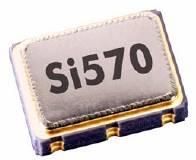
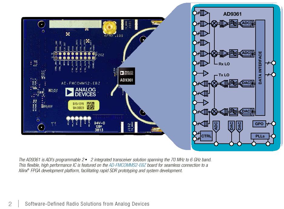
The Si570 is a relatively new device made by Silicon Labs. It's a very small device containing a crystal reference oscillator, digital Phase Locked Loop (PLL), and I2C interface so it can be programmed for any frequency between 10MHz and 945MHz (selected frequencies to 1.4GHz). Direct Digital Synthesis (DDS) chips such as those from the market leader Analog Devices have been around for longer. They are very different kinds of parts, even though they are both oscillators. Accordingly the best choice depends heavily on the application. These are my opinions about the relative advantages and disadvantages which may be important factors for your decision.
Projects
Experimental DDS project Si570-based QRSS transmitter
Reference data
Analog Devices DDS page
Analog Devices AD9910 DDS datasheet
Analog Devices AD9912 DDS datasheet
Silicon Labs
Si570 datasheet
Ease of Construction
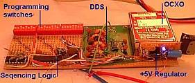
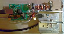
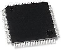
Package comparison (not to comparable scale):
AD9910 DDS (QFP100) Si570 (7 x 5mm package)
The Si570 wins here. It has 8 pins, and although a small surface mount package, you can still solder it reasonably easily, even with no PCB. On the other hand, all of the modern DDS devices are in surface mount packages only, for example this 100-pin AD9910 DDS. Soldering that one ugly-style would be a challenge. Even the earlier generation DDS's with 28 pin SMD's weren't easy.
Output waveform
The Si570 has a squarewave output. Often that's fine, for example, if you want to drive a mixer with it: many mixers operate best when the VFO is a squarewave. If you want a sinewave, you'll need a lot of low pass filtering to get rid of the rich suite of harmonics.
DDS chips have a sinewave output: it is generated by the rapid output of a succession of analogue voltages via a Digital-to-Analogue converter (DAC), which approximates a sinewave. Many of the DDS chips have an onboard comparator which can easily be used to turn the sinewave output into a squarewave, if that's what you need. Bear in mind though that you need an anti-alias low pass filter on the output of DDS chips to produce a clean output.
Which one wins... depends on your application. If you only need a squarewave, Si570 is fine. DDS can do either (if it is one of the ones which has a comparator on board), so for that reason, my winner is DDS.
Frequency range
A DDS will function right down to near DC. The practical upper range of a DDS is normally considered limited to 40% of its reference clock oscillator. This is a limitation of the digital synthesis of the waveform, which is a sampled process (look up Nyquist). Frequencies higher than 40% of the reference clock oscillator are also possible at the output of the DAC which is unfiltered, and these could be extracted by suitable bandpass filtering instead of the usual low-pass filter. Outputs like this require more detailed design and the performance is unlikely to be as good.
By contrast the Si570 allows any output frequency from 10MHz to 945MHz, and a more limited selection of frequencies all the way up to 1.4GHz. I have heard that operation below the specified 10MHz lower limit is possible too but have not confirmed this myself.
Here I'd say the DDS would win if you wanted to be able to go down to very low frequencies, but the Si570 would win if your application needs very high frequencies, or a very wide continuous range up to UHF and beyond. But because the Si570 has such a large and convenient range, let's call it the winner.
Frequency stability/accuracy
DDS requires a reference clock oscillator, which one normally provides with a high stability crystal oscillator. You have to provide the crystal reference oscillator. You can make it as accurate and stable as you like. GPS-lock it, lock it to a Rubidium standard, put it in a constant-temperature oven... whatever you like.
The Si570 has its own crystal oscillator built in. The difference here is that you have not much control over the internal oscillator of the Si570. You can't adjust it to be exactly on frequency, you can't lock it to a frequency standard or GPS reference. (It does have some frequency adjustment via an ADC input, but you'd still need to measure the actual frequency, compare it to a standard, and estimate a correction voltage - so it doesn't really do the job except with extreme effort). In my Si570-controlled QRSS beacon I found that the Si570 was already quite accurate and stable: A few Hz off frequency at 10.140MHz and it did not seem to drift perceptibly with room temperature variations, though neither of these measurements were detailed.
In my opinion, if you need stability and accuracy, DDS wins here, because you can make it as accurate and stable as you like.
Frequency agility
The frequency of a DDS can be set almost instantly (at least, as fast as you can clock your new desired frequency into the chip)! Most DDS chips have at least 32-bit tuning word resolution, and some of them even have 48-bit tuning word (e.g. AD9912) giving you tuning resolution down to steps of a few micro-Hz, if you should ever need it!
Si570's can also be tuned in very small steps but the frequency does not change instantly. When you make a change in frequency, there is a delay of up to 10ms (0.01s) while the internal PLL locks on to the new frequency. That can sound like a small click/chirp in your receiver audio for example, if you are using the Si570 as your receiver VFO. The Si570 can also be tuned much faster (100 times faster) for small steps within 3,500 parts per million (ppm) of the centre frequency. In this case, the settling time is less than 0.1ms (100us).
This delayed tuning of the Si570 might make it unsuitable for some applications, e.g. digital communications modes where the frequency must be changed quickly, or split frequency operation, or perhaps QSK CW with an offset between receive and transmit (though this would be unlikely to exceed the 3,500 ppm needed for a large-step).
So for frequency agility, the DDS definitely wins if your application needs it: frequency changes are as good as instant!
Programming interface
The DDS chips have a serial programming interface, and programming is easy. Some also support a parallel programming interface (one byte at a time). I built a DDS generator which can be done without a micro-controller at all (see here) but normally you'd be using a microcontroller.
The Si570 has an I2C interface, and programming the frequency you want is a little more tricky - involving some calculation of different multiplier/divider values and the internal digitally-controlled-oscillator frequency. A little more complex than the DDS programming word, which is a simple fraction of the reference clock frequency.
The Si570 is still not a problem if you're reasonably competent with programming microcontrollers, but as the DDS is more straightforward it has the lead here, I think.
Performance: Spurs
The Si570 is a digital phase locked loop oscillator producing a squarewave output. As all squarewaves, this is a fundamental plus a rich comb of odd harmonics. If a sinewave is required and the range of operation is narrow, the spurs can be filtered out if required, and are of course a reasonable distance from the carrier (i.e. at 3, 5, 7... times the fundamental carrier frequency). There is some harmonic content on even harmonics too as the output is not guaranteed to be a perfect 50% square wave. Other spurious responses are very low for the Si570 and not normally considered to be a problem.
DDS chips have a bad reputation for spurs! This is because the output sine waveform is approximated by a series of discrete steps, which are later filtered external to the chip by your low pass filter. The process is inherently a discrete appoximation of the ideal sinewave, which generates spurious responses. The spurii are numerous and at various different amplitudes, and also can occur very close to the carrier, so you cannot filter them all away.
Some of the most modern Analog DDS chips include a "SpurKiller" technology, such as the AD9912 with two SpurKiller channels. These are effectively two parallel DDS cores, whose frequency and output amplitude and phase can be set up such that if your application can predict or measure the location of your spurs, you could choose your two most objectionable spurs, and eliminate them by cancelling them out. I think the range of instances that this would be useful would be somewhat limited. The datasheet mentions that this feature performs optimally slightly differently on each device, which would further limit its usefulness in many practical applications.
The seriousness of the spurs problem depends mainly on two factors: the resolution of the DAC and the proportion of the output frequency relative to the reference oscillator frequency. DAC's typically go from 10-bits in some earlier devices up to 14-bits in a top-of-the-range device like the AD9912. A higher resolution DAC produces less spurs. Similarly if the reference oscillator frequency is very high relative to the output frequency, spurs are reduced. The AD9912 can operate with up to a 1GHz reference oscillator. For output frequencies in the 0-30MHz HF range, the spurs are very minimal. For VHF or UHF output frequencies the spurs could be more objectionable for sure. For amateur radio use, even on a low-end DDS, spurs are unlikely to be a problem in purely transmit applications, because they are less than the legal spurious output limits of amateur radio equipment. In receive applications, spurs will show up as birdies in the receiver, and are more serious. However, for an HF receiver if you were using a modern DDS such as the AD9912 with 1GHz reference clock oscillator, then the spurious content would be very low and unlikely to be noticeable in most cases.
A high-end DDS with careful design hasn't got spurious response problems under a limited range of circumstances i.e. at HF. But the Si570 wins on this one because it doesn't have spurs problems anyway.
Performance: Phase noise
Phase noise can be imagined as a widening of the theoretical perfect vertical line you would see on a spectrum analyser examining the output signal. One reason why it is important in a receiver, is that it mixes with strong signals some kHz away from your wanted signal to produce an elevated noise floor, which could easily obscure a weak signal you want to listen to. For a high performance receiver, it is really important to use a low phase noise local oscillator.
The phase noise performance of DDS is generally very good. There is a little jitter added by the imperfections inherent in the digital waveform approximation and some general very limited phase noise added by the imperfections of this digital device. Also the DDS phase noise can only ever be as good (actually slightly worse) than the reference clock oscillator. Typically this would be a crystal-based crystal oscillator, and crystals, being very high Q devices, have very good phase noise performance. So generally, DDS is considered a low phase-noise technology.
Many of the DDS chips include a reference clock multiplier PLL. This can be used to provide an internal very high frequency reference clock, up to the rating of the device e.g. 1GHz for the AD9910, from a much lower input clock oscillator frequency. Remember that high reference clocks are best, for best spur performance, so the multiplier can be useful in that regard. It can simplify your design greatly, but it comes at the price of adding unwanted phase noise in the internal PLL multiplication process. Frequency multiplication in any event carries a theoretical minimum 6dB/octave (or 20dB/decade) phase noise penalty, but if you use the internal PLL multiplier you add even more than this. So for best phase noise performance, leave the PLL switched off and build your own external high frequency reference oscillator.
The Si570 is based on a PLL technology, which generally has a much higher phase noise. However in the Si570, they minimise the phase noise by careful design and by using a very narrow loop bandwidth. This is the reason why it has a relatively slow settling time (10ms) when you change the frequency. So the phase noise of the Si570 is pretty respectable, and will probably be adequate for many applications.
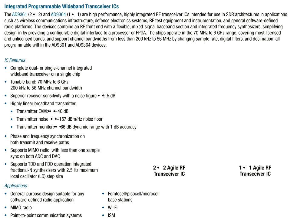
How about a comparison between DDS and Si570? The phase noise performance data in some of the DDS datasheets is somewhat limited. Often they show the "residual phase noise", which means the additional phase noise which is added to that of the reference oscillator by the DDS process itself. This is not the same as the actual phase noise you would observe on the output - for that you need to also add the phase noise of the reference oscillator - so it is not directly comparable with the phase noise of an Si570. However, some of the DDS device datasheets show an absolute phase noise chart, and an example of this is the AD9912 which shows output phase noise for various output frequencies and assuming the use of a high performance 1GHz Wenzel oscillator. The Si570 datasheet has a table of phase noise at three output frequencies (120MHz, 156.25MHz, 622.08MHz).
It is important to remember that when a frequency is divided, the phase noise also decreases by 6dB per octave (or, 20dB per decade). So in any comparison, we need to take this into account if the frequencies concerned are not the same. For this example comparison, I am choosing to compare the Si570 data at 156.25MHz with a graph in the AD9912 datasheet at 171MHz. Strictly I should adjust for this frequency difference (i.e. 156.25MHz and 171MHz) by doing some mathematics for the 6dB/octave. However they are close enough frequencies that this would make only 1dB difference or so, which in any event is only about the precision I can read off the values from the chart in the AD9912 datasheet, so I'm going to ignore it for now. This small inaccuracy would act in favour of the Si570 which is at the lower frequency in this comparison.
So, here's a table of the values for 156.25MHz from the Si570 datasheet, and the corresponding values read off the graph from the AD9912 datasheet. These results would be expected to be broadly repeatable with the two devices at other frequencies, appropriately scaled by 6dB/octave (20dB/decade). The units of phase noise are dBc/Hz.
Offset Si570 AD9912
100Hz -105 -125
1kHz -122 -138
10kHz -128 -148
100kHz -135 -157
1MHz -144 -162
10MHz -147 -163
Here are those same results, represented on a graph:
The overall conclusion here has to be that a top-end DDS with quality reference clock oscillator and good design (the AD9912 at 1GHz refclk), can outperform the Si570 by 20dBc/Hz. However, I'd say that for many applications the Si570 phase noise performance would be sufficient, and probably better than many expensive commercial "black box" amateur radio transceivers on the market.
But due to the excellent phase noise performance of DDS technology, DDS is the winner here.
Power Consumption
Neither the Si570 nor DDS are exactly innocent when it comes to power consumption. Both will be agressively trying to drain your batteries, if you are operating battery-powered equipment.
The Si570 is stated to consume 120mA at 3.3V for the LVPECL, which is 396mW. An AD9912 on the other hand, requires separate voltages at 1.8V and 3.3V for its various sections (analogue and digital). Each has different current consumption, but the datasheet also lists typical power consumptions under various configurations. The power consumption is between 637mW and 747mW. The AD9912 even has an exposed copper pad on the bottom to help get the heat out! Don't forget, this is even before you consider that the Si570 has its own internal reference clock oscillator, whereas DDS chips needs you to provide one externally, which will add even more power.
Some of the older, less powerful DDS chips do consume less power. But as I've mentioned the top of the range DDS devices a lot, particularly the AD9912, I'll say that the Si570 wins on this measure.
Cost
Neither are cheap. The Si570 is a similar price to some of the lower-end DDS chips but for a high-end DDS such as the AD9910 or the AD9912 I keep mentioning, you'll be paying considerably more than for the Si570. Also the DDS require more support circuits such as the reference clock oscillator, which is also unlikely to be cheap. On the other hand, if you're a cunning (and stingy) radio amateur, you used to be able to get free DDS samples from Analog. You never could get free Si570 samples from SiLabs. Overall I think we have to say the Si570 wins on cost, generally.
Other features
The Si570 is just a plain oscillator. If you want more features, you want a DDS! Read the datasheets, and be amazed! Control the amplitude, control the phase, add spur killing. Some DDS devices contain TWO cores and outputs, which can be set to be offset at 90-degree phases (useful for phasing direct conversion mixers for example - check out the AD9854). Automate your amplitude modulation, frequency modulation, phase modulation, automatic sweep, and other kinds of features I can't even remember or understand. You probably don't need them, they're probably just sales gimmicks, but on features you have to agree, the DDS is definitely the winner.
Overall complexity
An Si570 is pretty simple to use. Just add a 3.3V power supply, connect up your microcontroller, and you're ready to go.
Not so, the DDS! With a DDS you may need four separate well-regulated and clean power supplies, some at 1.8V and some at 3.3V. You need a reference clock oscillator. Some DDS chips have an onboard oscillator where you can just connect the crystal directly to the chip. But for best performance you'll want to design and build a 1GHz oscillator, which is no trivial matter, and get that properly coupled into the chip input. Then you need the reconstruction filter (typically low pass) at the output, and that needs to be carefully designed too. The board design needs lots of care too, with all that high frequency stuff rolling around.
Yes, using a DDS is a lot more effort than an Si570. So on complexity, the Si570 is definitely the winner.
Summary
So after all that, here's my summary of my opinion on the various criteria by which to judge these two kinds of oscillator. Bear in mind that every application is different! In some applications, some of these criteria don't matter to you at all, or the decision of what is better will be clear (and opposite to my conclusion). In others, you are faced with the usual decisions about trade-offs. Performance and complexity; features and cost; etc. But I'll generalise and operate in typically bi-polar manner and give my overall winner in every category regardless, and leave the judging of your applications to you.
Category Winner
Ease of construction
Si570
Output waveform DDS
Frequency range Si570
Frequency stability/accuracy DDS
Frequency agility DDS
Programming interface DDS
Performance: Spurs Si570
Performance: Phase noise DDS
Power Consumption Si570
Cost Si570
Other features DDS
Overall Complexity Si570
Further reading
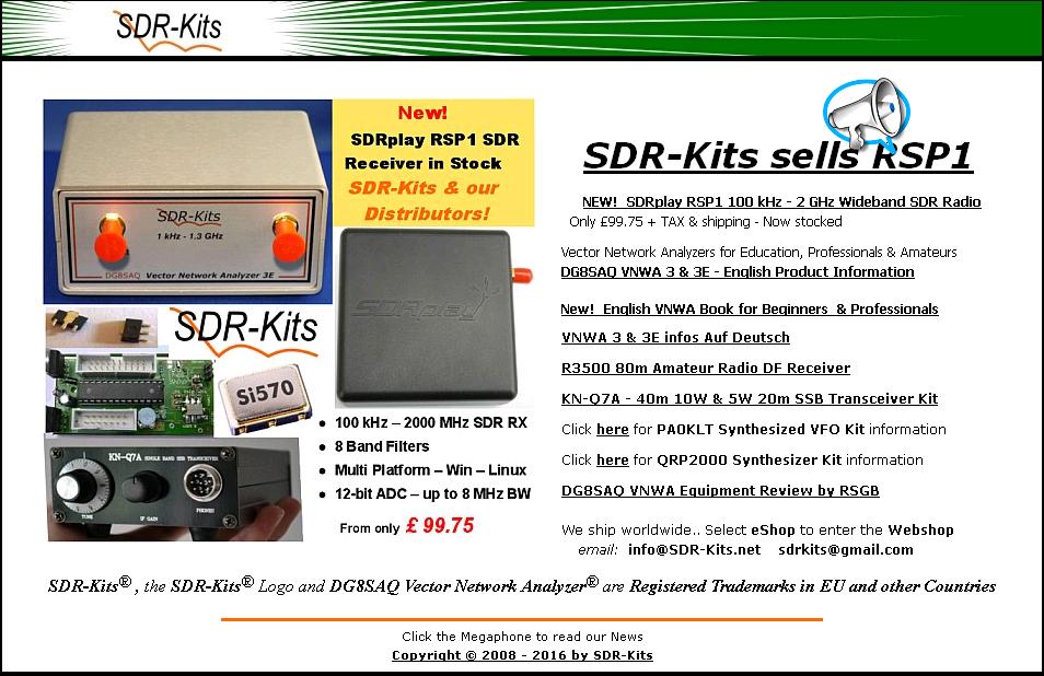
For a great inspiring read about a wonderful ultimate-high-performance receiver project, and the reasons why Martein PA3AKE chose the AD9910 DDS for his oscillator, please visit his site. For Si570 kits see SDR Kits. There are loads of DDS kits around, just google for them. For lots of interesting info and discussion about the Si570, visit Andy G4OEP's Si570 pages; like Martein PA3AKE, Andy never does anything by halves.
My Favourite
What's best really depends on the application. But if you're still reading this, and I have to choose a general overall favourite, I just have to choose the DDS. Just like a favourite colour, or a favourite lucky number, I don't need a good reason. I just LIKE it better!
Last Updated on Monday, 03 March 2014 04:54
ورود کاربران
عضويت سريع
پشتيباني آنلاين
آمار
خبرنامه
آخرین نطرات کاربران
 جواد یاور مطلق - درود
 بلا بدور باشه مهندس !
انشالله همیشه سرحال سالم تندرست باشید !
پاسخ:با درود و سپاس از لطف شما دوست گرامی بدرود - 1403/1/29
یک هم وطن - من بدون مدار این رادیو ساختم باصدای واضح و بلند بدون برق و باطری پاسخ:باتشکر از لطفتان امیدوارم بقیه دوستان هم همت کنند و دست به اچار و هویه شده خودشان بسازند و لذت ساختن را ببرند چون در داشتن لذت نیست هنر ساختن است - 1402/6/13
AEC - دروداستاد ممنون خیلی خوب و عالی
 پرویز مهرزاد - سلام درود جناب عبداحق عزیز بسیار خوشحالم که وب سایت شما با مطالب مفید وعالی فعال شده است.
پاسخ:باسلام و تشکر از لطف و مرحمت شما دوست عزیز و گرامی - 1400/8/28
پرویز مهرزاد - سلام ودرود استاد عبدالحق عزیز بسیار خوشحالم که سایت جنابعالی بامطالب جدید وعالی دوباره فعلیتش را شروع نموده است.پاسخ:با سلام تذکر بجا و بموقعی بود بسیار متشکرم - 1400/8/28
ایزدی - یه مشکلی داره این طرح. کل سلف ها با هم 12. 7 میکرو میشه که با خازن 270 پیکو، فرکانس مرکزی فیلتر 2.7 مگا هرتز می شه. کمترین سلف هم (0.1 میکرو) با همون خازن 270 پیکو 30 مگاهرتز رو رد می کنه. بنا بر این نیازی به خازن های دیگه نیست. دوستان دیگه نظرشون چیه.پاسخ:باسلام و تشکر کل خازن ها و سلفها برای فرکانس 1800کیلو که ابتدای باند رادیو اماتوری است کم است و بسختی تنظیم می شود اما برای 3500 بله زیاد است - 1399/8/24
هومن - سلام .علت استقبال نکردن در خور توجه همین نا واردیست .این مطلب بسیار گنگ و پر از اشتباه هست پاسخ: سلام بنده هم ضمن تائید نظر شما درخواست می کنم مطلب کامل تر و بهتر و درست تر را بفرمائید بنده بنام خودتان درج و منتشر نمایم
پاسخ:https://t.me/joinchat/AAAAAEJj30AwLGIyi_UQ3g مدارات لامپی - 1396/12/17
علی - سلام شما مکتبی و انقلابی هستید درسته ؟پاسخ: سلام بهیچ عنوان و تقریبا هیچ جائی من چنین ادعائی نکرده ام اما این همه شهید و زخمی و جانباز و اسیر و زحمت و فعالیت برای حفظ انقلاب و سرزمین عزیزمان ایران خیلی حرام لقه گی و بی اصل و نصبی می خواهد که چشم خودرا ببندیم و از این اب و خاک حمایت و به این مردم عشق نورزیم حالا شما اسم انرا هرچه دوست دارید بگذارید نظرتان محترم است - 1396/12/17
هومن - سلام بنده یکی از علاقمندان لامپ هستم . و 10 سال اخیر را بر روی مدارات لامپی کار کردم .با سرچ اینجا را پیدا کردم .می خواستم ببینم در زمینه مخابرات فعالیت لامپی در ایران هست ؟
این مطلب راجب لامپ واقعا توجه مخاطب علاقمند را جلب می کند ؟
من فکر می کنم نویسنده اصلا راجب لامپ حس خوبی ندارد .عذر خواهی می کنم
پاسخ:سلام دوست عزیز از صراحت و فصاحت بیان شما خوشحالم مطلبتان راجع به نویسنده مطلب لامپ کمی کم لطفی و شاید سخت گیری در بر دارد نویسنده مطلب استاد عاملی بزرگ رادیو اماتوری ایران هستند و مطلب را بی اندازه ساده و اسان گفتند چون اکثر جوانها از لامپ و ولتاژ کار ان وحشت داشته و تقریبا هیچ نمی دانند اما ظاهرا شما در مورد لامپ مطلع و ازموده هستید لذا برخود نگیرید شما هم اگر در مورد لامپ و یا مطالب استاد عاملی نقد و نظری دارید بسیار خوشحال می شوم مکتوب بفرمایید تا در همان بخش یا در بخش جدید بنام خودتان منتشر شود
پاسخ:https://t.me/joinchat/AAAAAEJj30AwLGIyi_UQ3g - 1396/12/16
سعیدی - سلام استاد بنده بی جواب ماندم پاسخ:با سلام و پوزش از تاخیر طبق تجربه دوستان این مدار به دلیل نامرغوب بودن قطعات نو موجود در بازار معمولا در ابتدا کار نمی کند لذا بتوصیه استاد عاملی بهنر است از قطعات اوراقی رادیو و ضبط ها استفاده شود قطعات معمولا در گیر این رادیو ابتدا ای سی سویچ یا کلید زنی است که یک مدل خاصش برای مدار مناسب است و مدلهای دیگر فرکانس کار و ولتاژشان مناسب نیست درمورد ای سی مدولاتور و دمدولاتور 3028 این ای سی هم بشدت مورد شک و شبهه است در موردی باتعویض 5 عدد ای سی دو عدد که بهتر بود در مدار بکار گرفته شد لذا بهترین روش استفاده از مرحله مرحله و گام بگام کار کردن رادیو است ضمن انکه اگر فرستنده کار بیفتد گیرنده هم کار خواهد کرد و بالعکس لذا شما می توانید مدار را از میکروفون در حالت فرستنده یا بلندگو در حالت گیرنده شروع نمایید و اگر مسیر سیگنال جدا باشد در نقشه شما می توانید از تقویت صدا شروع کرده و به دمدولاتور رفته و سپس به فیلتر و بعد میکسر وی اف او و در اخر به فیلتر تنظیم باند بروید و حد اکثر سیگنال و حساسیت را بدست اورید پس فیلتر های رادیویی یا بقول شما توکو ها قسمت اخر تنظیم و تعقیب مدارتان است اگر شد برای اطلاع شما و سایر دوستان مدار را در حالت گیرنده و فرستنده جدا اراعه خواهم داد یا با رنگ مسیر سیگنال را جدا می کنم که راحت تر باشد اگر شما عضو تلگرام هستید در یکی از گروه های رادیو اماتوری بیایید و مستقیما با دوستان سازنده و استفاده کننده رادیو تماس گرفته راهنمایی شوید اگر نه ادرس ایمیلتان را بدهید تا راهنمای مونتاژ را برایتان بفرستم
پاسخ:http://py2ohh.w2c.com.br/trx/ararinhamontagem/montandoararinha.htm
راحل مونتاژ و تست مدار است - 1396/11/5
آرشیو
- شهريور 1404
- تير 1403
- مهر 1402
- ارديبهشت 1401
- دی 1400
- آبان 1400
- ارديبهشت 1399
- اسفند 1397
- آذر 1397
- آبان 1397
- خرداد 1397
- ارديبهشت 1397
- فروردين 1397
- اسفند 1396
- بهمن 1396
- دی 1396
- آذر 1396
- آبان 1396
- شهريور 1396
- مرداد 1396
- تير 1396
- خرداد 1396
- ارديبهشت 1396
- فروردين 1396
- اسفند 1395
- بهمن 1395
- دی 1395
- آذر 1395
- آبان 1395
- مهر 1395
- شهريور 1395
- مرداد 1395
- تير 1395
- خرداد 1395
- ارديبهشت 1395
- فروردين 1395
- اسفند 1394
- بهمن 1394
- دی 1394
- آذر 1394
- آبان 1394
- مهر 1394
- شهريور 1394
- مرداد 1394
- تير 1394
- خرداد 1394
- ارديبهشت 1394
- فروردين 1394
- اسفند 1393
- بهمن 1393
- دی 1393
- آذر 1393
- آبان 1393
- مهر 1393
- شهريور 1393
- مرداد 1393
- تير 1393
- خرداد 1393
- ارديبهشت 1393
- فروردين 1393
- اسفند 1392
- بهمن 1392
- دی 1392
- آذر 1392