سلام روزتان بشادی
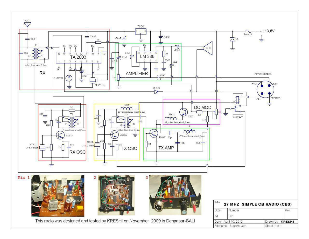
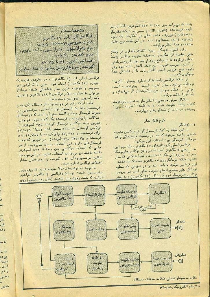
طرحی از رادیوی 27 مگا توسط مهندس علیرضا سیفی ترجمه و در گروه رادیو اماتوری اراعه گردید که بدلیل سادگی تقدیم دوستان می گردد در صورت علاقه سوال یا توضیح یا راهنمایی اگر لازم بود اماده پاسخ گویی توسط اعضای محترم گروه و استادان 27 مگا یا بقول دوستان فرکانس مهندس عاملی هستم


QRP 8W @ 13.8V 1.35A
40m band
This is the end of ARARINHA project, I will add CW and further others bands.
ARARINHA is simple to build and to adjust, I will describe the circuit and add details and tips of building.
This schematics is the ARARINHA 4 normal.

سلام
دوست عزیزی درخواست رادیو 27 مگا با مشخصات زیر کردند:
سلام جناب عبالحق بنده از علاقمندان راديو اماتوري هستم اگر ميشه نقشه يك واكي تاكي 1وات رو فركانس 27mhz با نقشه ومدار چاپي با استفاده از كريستال27mhz با اختلاف 455khzبگذاريد
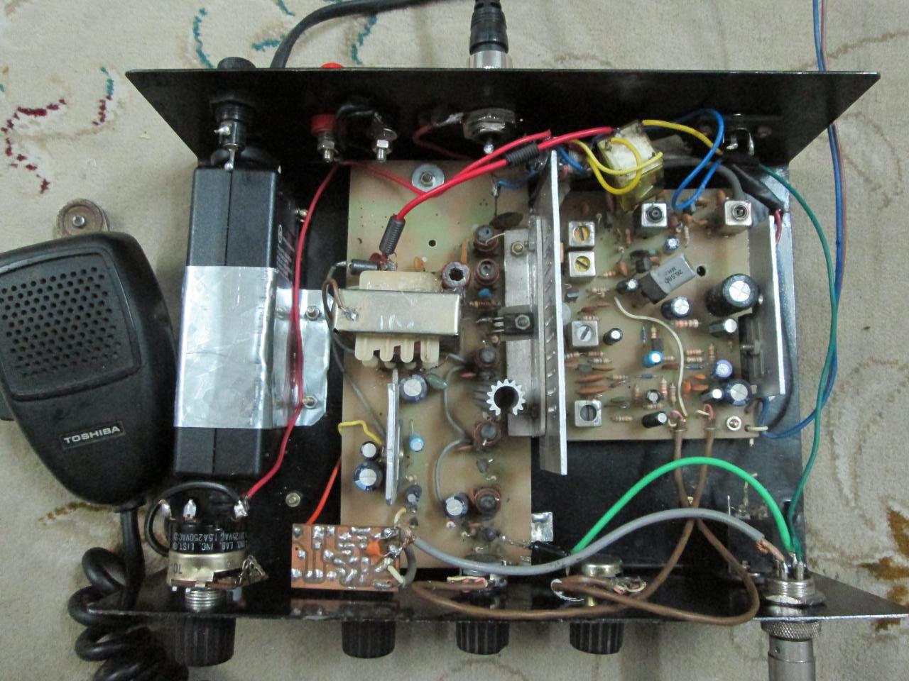
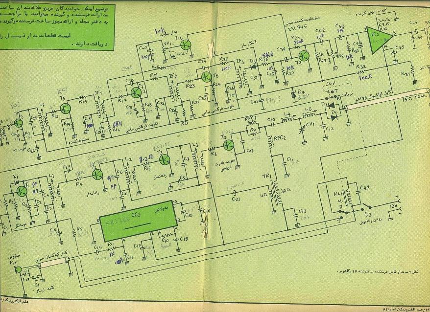
در اجرای امر این عزیز رادیوی 27 مگای با ای اف 455 کیلو ساخته برادر بزرگوارمان جنابمهندس دلقوی را اراعه می نمایم
هرگونه توضیح و راهنمایی هم از طریق ایشان یا مکاتبه قابل انجام می باشد ضمنا این رادیو در فرکانس 27035 کیلو یا کانال 7 فعال و بگوش می باشد
جناب دل قوی فرموده اند:
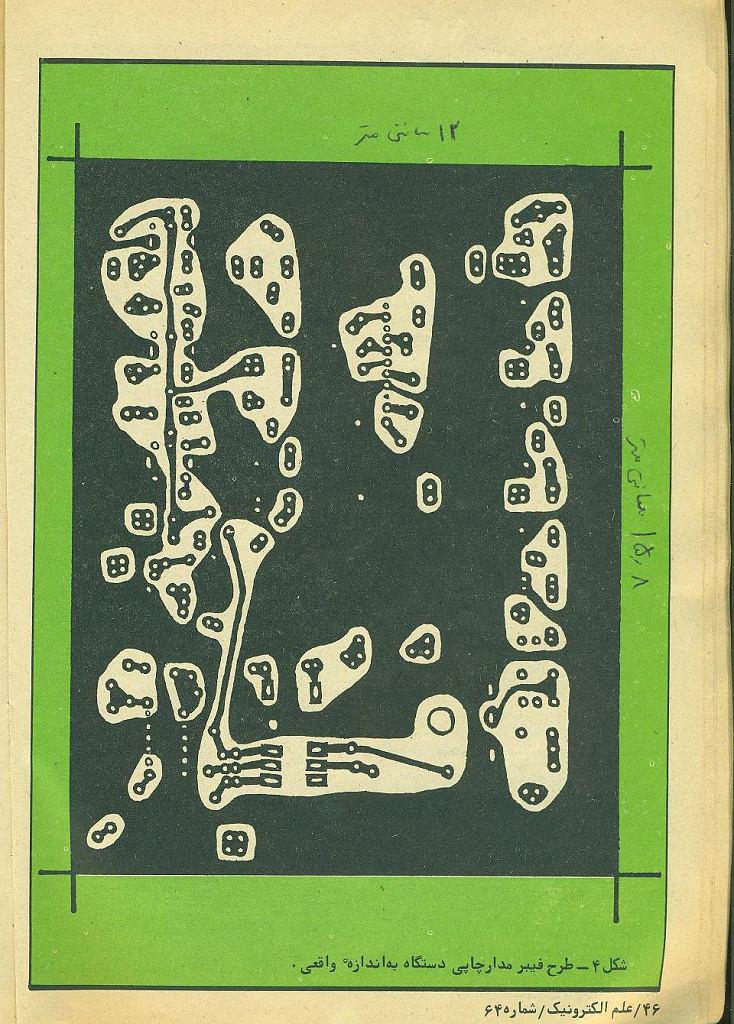
من نقشه فرستنده 27 مگاهرتز استاد عاملی را درست کردم و تمامی نقشه ساخته شده و فیبر موجود است اما قدرتش 4 وات است و ایشان می تواند طبقه اخر را حذف کند و مدار در عمل می شود 1 وات
با سلام
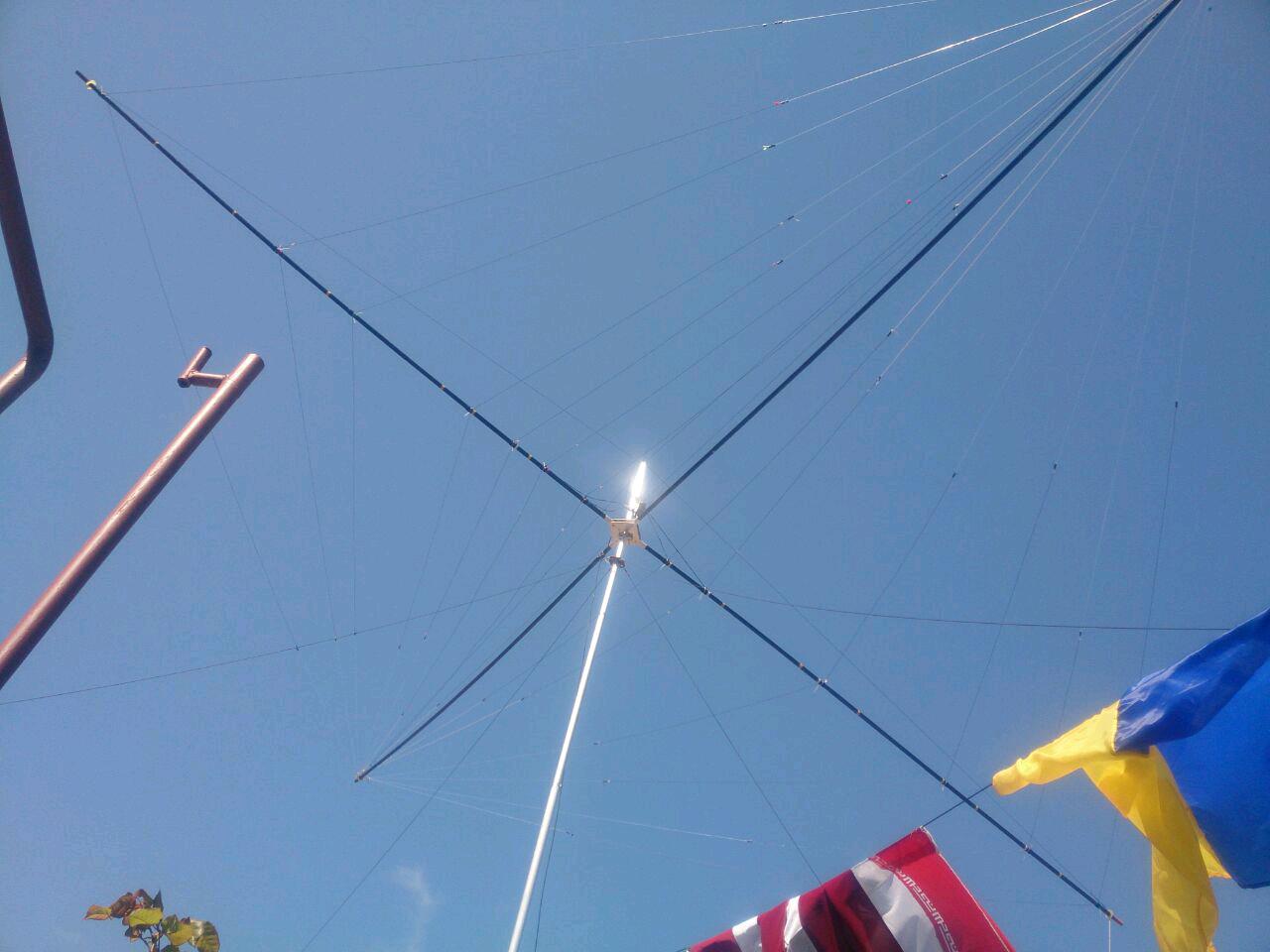
فعالیت یک روزه کلوب رادیوآماتوری البرز (EP2C)
کلوب رادیوآماتوری البرز (EP2C) قصد دارد در راستای :
# گسترش فعالیت های رادیوآماتوری در ایران
# برپایی سریع ایستگاه رادیویی در شرایط بحران
# آموزش (برپا کردن و تیون آنتن، تنظیم و راه اندازی تجهیزات رادیویی، نحوه برقراری تماس رادیویی و مورس و ساخت آنتن های مختلف
# امکان برقرای تماس با رادیوآماتورهای ایرانی توسط رادیوآماتوری های بین المللی
فعالیت یک روزه ای را در تاریخ شنبه ۲۶ تیر ۱۳۹۵ در ارتفاعات کرج برگزار نماید.
این برنامه از ساعت ۵ صبح شروع شده و بر روی باندهای ۱۰، ۱۵ و ۲۰ متر تا ساعت ۲۱ شب ادامه خواهد داشت،
پیشاپیش از حضور تمامی دوستان رادیوآماتور یا علاقه مند به رادیوآماتوری استقبال می کنیم. در صورت تمایل به حضور و اطلاع از آدرس دقیق محل برگزاری، با آقای محمد عظیمی (EP2LMA) یا سعید شکراللهی (EP2LSH) تماس بگیرید.
حضور در این برنامه، برای افراد علاقه مند به رادیوآماتوری بسیار آموزنده و مفید بوده و افراد از نزدیک شاهدبرپایی ایستگاه و نحوه برقراری تماس های راه دور خواهند بود.
بدیهی است برنامه مذکور در چهارچوب قانون و با اخذ مجوز از سازمان تنظیم مقررات و ارتباطات رادیویی و با هماهنگی دیگر ارگانهای ذیصلاح برگزار می گردد.
www.ep2c.ir
@alborzdx
Alborz dx group | First Iranian dx group
The EP2C club will be active on 16 July (Saturday) in Karaj’s heights (Karaj is a city 30Km north-west of Tehran) The primary motivations for this activity
با سلام مطلب جالبی از گروه البرز بدستم رسید که تقدیم دوستان می شود
مدیریت تماس های DX
توسط: Mehdi در مقالات مارس 10, 2016 295 نمایش
رادیوآماتوری هم مثل بسیاری از علوم و فنون و رشته های تفریحی، ادبیات و اصطلاحات خاص خودش رو داره. کلمات و اصطلاحاتی مثل ham، rig و DX، کد های سه حرفی که با Q شروع میشن (مثل QRP، QSL …) ، مثال هایی از این اصطلاحات هستن.
این مقاله در مورد آشنایی با کلیات و اصطلاحات مربوط به کار با رادیوآماتورهای دور (distant) هست که اصطلاحا بهش DX گفته میشه و مطالب مهم رو به صورت نکته وار در مقاله ارائه می کنم.
ابتدا مروری داشته باشیم به اختصارات استفاده شده در این زمینه:
DX: تماس رادیویی با افرادی که از نظر جغرافیایی از ما دور هستن (DX یک اسمه و فعلش DXing هست)
DXer: کسی که با یک ایستگاه دور ارتباط برقرار می کنه.
نکته ۱: DX میتونه شنیدن و تلاش برای دریافت ایستگاه های دوردست هم باشه و همچنین محدود به محدوده فرکانس HF نیست، اما در این مقاله ما صرفا در مورد تماس های رادیویی دو طرفه در محدوده HF به منظور تماس با نقاط و کشورهای دوردست صحبت می کنیم.
نکته ۲: حرف D در DX مخفف distant هست. بنابراین صحبت کردن یک ایرانی با یک فرد عمانی یا روسی بر روی رادیو، جزو DX محسوب نمیشه و با توجه به موقعیت کشورمون، صحبت با کشورهای قاره آمریکای شمالی و جنوبی و همچنین جنوب شرقی آسیا (مثل ژاپن) و استرالیا و نیوزیلند جزو تماس های DX برای ما محسوب میشه.
نکته ۳: DX لزوما صحبت نیست و میتونه بر روی دیگر مدها (مثل مورس) هم صورت بگیره. اتفاقا مورس (CW) به خاطر حداکثر استفاده از توان خروجی فرستنده و همچنین فرکانس، یکی از بهترین مدولاسیون ها برای ارتباط با ایستگاه های خیلی دوره.
DXpedition: سفر چندین رادیوآماتور به یک نقطه جغرافیایی و تماس برقرار کردن از اونجا (معمولا نقاط دوردست یا جاهایی که فعالیت رادیوآماتوری در اون ها برگزار نمیشه، کاندیداهای خوبی برای این کار هستن. مثل کشورهای فقیر و کم جمعیت، جزایر مختلف، مکان های بسیار دور در دل طبیعت و …)
pileup یا تجمع: وقتی یک ایستگاه رادیویی شروع به CQ زدن می کنه، ممکنه تعداد زیادی رادیوآماتور بخوان با اون فرد صحبت کنن و تماسشون ثبت بشه (به خصوص کشور ایران به خاطر این که فعالیت رادیوآماتوری کمی داره و افراد فعالش کمتر از ۱۰ نفر هستن). به این وضعیت که در واقع تجمع تعداد زیادی رادیوآماتور برای صحبت با فردی هست که CQ زده، pileup گفته میشه و یکی از مهارت های یک رادیوآماتور خوب
و در واقع یکی از ویژگی های متمایزکننده یک رادیوآماتور خوب از یک رادیوآماتور معمولی، توانایی اون در مدیریت این وضعیت هست تا بتونه به خوبی و به نوبت جواب همه رو داده و از جروبحث یا اشغال بیخودی فرکانس و ایجاد همهمه جلوگیری کنه.
در واقع بقیه این مقاله به مساله مدیریت pileup و یک تماس خوب DX می پردازه.
یک DX و یک pileup خوب و منظم، نشان دهنده مهارت اپراتور برگزار کننده DXpedition هست که مهم ترین ویژگی، مسئول بودن و توان مدیریت هست. یادتون باشه وقتی CQ می زنید، این شما هستید که قوانین رو تعیین می کنید و باید جدی ولی مودبانه این مساله رو مدیریت کنید (به عنوان مثال ممکنه موقتا فقط با یک قاره خاص یا یک کشور خاص بخواید تماس داشته باشید و از دیگر اپراتورا بخواید که تا یک زمان مشخص شده، تماس نگیرن تا شما با اون کشور مدنظر قادر به تماس باشید. نمونه بارز این مساله، ایجاد نویز و مزاحمت و شلوغ کاری توسط اپراتورهای اروپایی هست که مانع از صحبت آسیایی ها با آمریکا میشن و اپراتورهای کشورهای ایتالیا، روسیه و اوکراین سهم مهمی در این بی نظمی دارن.)
مهارت بعدی یک اپراتور DXer خوب، زبان انگلیسی هست. البته این مساله رو مدنظر داشته باشید که بسیاری از اروپایی ها، ضعف زبان انگلیسی دارن و هیچ وقت پیش فرض ذهنی رو بر این اساس قرار ندید که تمامی رادیوآماتورها مسلط به زبان انگلیسی هستن. البته ضعف زبان انگلیسی در اپراتورهای دیگر کشورها مثل ژاپن هم وجود داره اما فرهنگ مردم این کشور مانع از ایجاد بی نظمی توسط اون ها میشه
نکته بعدی اینه که حتما در بازه های مختلف زمانی، مجددا کال ساین خودتون رو اعلام کنید تا کسانی که جدید هستن، نیازی به پرسیدنش نداشته باشن (صحبت کردن با افراد در pileup و زمانی که همه منتظر هستن، متفاوت تر از صحبت در یک تماس عادیه و حتما باید با حداکثر اختصار و صرفا رد و بدل کردن سیگنال ریپورت انجام بشه تا تعداد زیادی تماس رو بشه ثبت کرد و همچنین افراد زیادی بی جهت در صف نمونن)
برای افزایش احتمال تماس با کشورهای مختلف، تمامی باندهای مجاز رو تست کنید. باندی که در ایران بیشترین استفاده رو داره، ۲۰ متره، اما از سه باند مجاز دیگر غافل نشید (به خصوص ۴۰ متر که کمترین استفاده رو در ایران داره اما در کشورهای دیگر به خصوص آمریکا محبوب هست)
دقت کنید که در pileup ها برخی از افراد با قدرت ارسال زیاد (در حد کیلووات) بدون رعایت نوبت و صف، میخوان با شما صحبت کنن (که روس ها و ایتالیایی ها نمونه بارزشون هستن). در صورت امکان جوابشون رو ندید و ازشون بخواید منتظر بمونن. اما اگر دیدید طرف مقابل همچنان به رفتارش ادامه میده، سریع باهاش صحبت کنید تا مزاحمتش تموم شده و بتونید به صحبت با بقیه ادامه بدید.
زمان هایی که نیاز دارید صحبت یک نفر رو بشنوید، حتما با متانت و ادب، کال ساین اون رو اسم برده و از بقیه بخواید ساکت باشن تا بتونید تماس موفقی داشته باشید.
دقت کنید که برخی از اپراتورهای اروپایی ممکنه مزاحمت ایجاد کنن (مثلا با سوت زدن با توان زیاد بر روی فرکانس شما). در صورت به وجود اومدن و ادامه داشتن این نویزها (که DQRM یا نویز عمدی نامیده میشن)، میتونید فرکانس رو عوض کنید، اما قبلش باید حتما این مساله رو اعلام کنید تا بقیه هم بدونن و به فرکانس جدید بیان.
نکته بسیار مهمی که رادیوآماتورهای ایرانی رعایت نمی کنن و در یک DXpedition الزامیه، کار کردن در حالت split هست.
تمامی ترنسیور های مدرن (تولید شده از ۲۰ سال قبل تا الان) دارای این ویژگی هستن که اغلب هم یک دکمه به نام Split روی دستگاه دارن. split mode operation در واقع به حالتی گفته میشه که فرکانس ارسال و دریافت یکسان نیستن.
مثال: شما بر روی ۱۴٫۲۰۰ مگاهرتز ارسال کرده و جواب ها رو بر روی ۱۴٫۲۰۵ دریافت می کنید.
مزیت این حالت در این هست که تنها کسی که روی فرکانس ارسال (۱۴٫۲۰۰ در مثال فوق) صحبت می کنه، شما هستید و بقیه برای صحبت با شما باید دستگاهشون رو طوری تنظیم کنن که بر روی فرکانس دریافت شما (۱۴٫۲۰۵ در مثال فوق) ارسال داشته باشن و بالعکس. معمولا در حالت SSB، این فاصله رو بین ۵ تا ۱۵ کیلوهرتز انتخاب می کنن. ضمنا نحوه CQ گفتن هم متفاوت خواهد بود. مثال:
CQ CQ CQ EP2C 5 Up
یعنی من روی این فرکانس فعلی (هرچه که هست) در حال CQ زدن هستم اما روی ۵ کیلوهرتز بالاتر دریافت می کنم.
حتما در split mode، در فواصل کوتاه تر زمانی، کال ساین خودتون رو اعلام کنید تا بقیه متوجه بشن که باید ۵ کیلوهرتز بالاتر جواب شما رو بدن (اگر هم متوجه شدید کسی روی فرکانس ارسال شما داره جواب میده، به هیچ وجه بهش جواب ندید)
بعضی وقتا میشه به منظور سهولت، قاره ها رو از هم جدا کرد. یعنی اعلام کنید که ۱ ساعت فقط با اروپا صحبت خواهید کرد و بعدش فقط با آمریکا و غیره. مزیت این روش، عادلانه بودن تماس ها و رسیدن نوبت به همه است.
حتما اگر قراره به صورت موقتی تماس ها رو قطع کنید و مثلا یک ربع بعد برگردید (برای استراحت، نوشیدن چای و …) این مساله رو اعلام کنید تا بقیه بدونن. یهویی غیب نشید. اگرم قراره کلا تماس رو در اون روز قطع کنید و دیگه برنگردید، باز هم اعلام کنید.
من این مقاله رو برای رادیوآماتورهایی نوشتم که تجربه صحبت رادیویی دوطرفه رو دارن. اگر یک تازه کار هستید، توصیه می کنم قبل از CQ زدن، مدت ها فقط روی باندهای مختلف گوش بدید تا یاد بگیرید آدمای حرفه ای تر چطور این کار رو انجام میدن.
خیلی مهم:رفتار مسئولانه و محترمانه در یک تماس رادیویی بسیار مهمه. این مساله در کل فرایند رادیوآماتوری (برقراری تماس، جواب دادن به بقیه، رد و بدل کردن کارت پستال و …) خودش رو نشون میده. یکی از مثال ها، یک رادیوآماتور ایرانی بود که درخواست مبلغی بیش از حد لازم جهت ارسال کارت پستال می کرد و با این وجود هم جواب نامه بسیاری از افراد رو نمی داد که باعث ایجاد نارضایتی در رادیوآماتورهای خارجی شده بود که این مساله رو در سایت ها و فروم های مختلف اعلام کرده بودن. مسائل این چنینی به پای کل رادیوآماتور های کشور نوشته میشه! (همونطور که روس ها و اوکراینی ها و ایتالیایی ها به خاطر رفتار بد عده قلیلی از اپراتورهاشون بدنام شدن)
پی نوشت:
نکته ای که به صورت غیرمستقیم به همین مقاله هم مربوطه، CQ زدن برای مسابقاته. وقتی شما در یک مسابقه CQ می زنید و دیگران باید با شما تماس بگیرن، حداقل ده دقیقه روی یک فرکانس خاص CQ بزنید تا به مرور pileup بشه. مسابقه اخیر در ایران (اولین مسابقه رادیوآماتوری که در دهه فجر سال ۹۴ برگزار شد) این نکته رو نشون داد که به غیر از چند نفر، بقیه رادیوآماتورا درک درستی از نحوه شرکت در مسابقه ندارن و به جای این که بر روی یک فرکانس ثابت CQ زده و منتظر جمع شدن دیگران باشن، از فرکانسی به فرکانس دیگر پریدن! از نشانه های یک CQ موفق، حجم زیادی تماس بر روی یک فرکانس ثابت هست، نه تعدادی تماس پراکنده روی فرکانس های مختلف)
ref.:
http://www.irandx.ir/1394/12/20/%D9%85%D8%AF%DB%8C%D8%B1%DB%8C%D8%AA-%D8%AA%D9%85%D8%A7%D8%B3-%D9%87%D8%A7%DB%8C-dx/
با سلام
در ذیل طرحی از یک اماتور روسی که در ان از مدار تطبیق امپدانسی استفاده کرده که هم با ال ای دی قدرت رفت یا برگشت را نشان میدهد و هم با استفاده از کلید و عقربه نسبت رفت امواج را به برگشتشان اندازه می گیرد
مدار خوبی است و تقریبا مشابه مدار تطبیق امپدانس رادیو اچ اف شرکت راکال انگلیس است
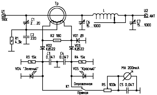
http://www.rigexpert.com/index?s=articles&f=aas
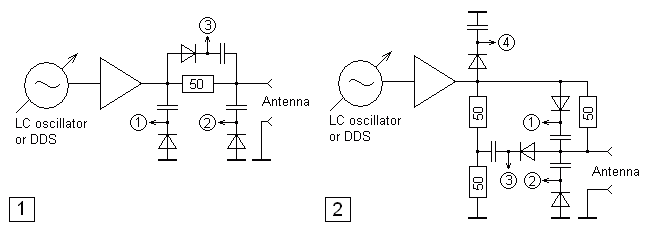
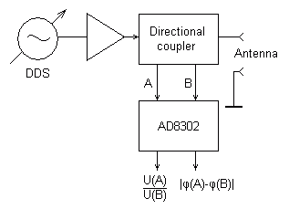
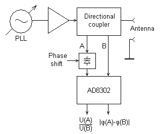
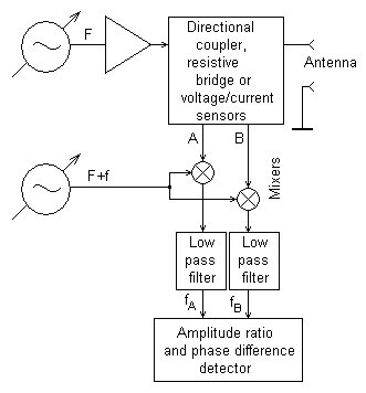
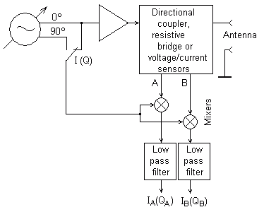
.gif)
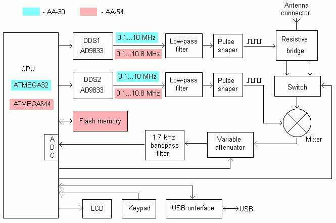
با سلام و تشکر از دوست عزیزم مهندس رسولی
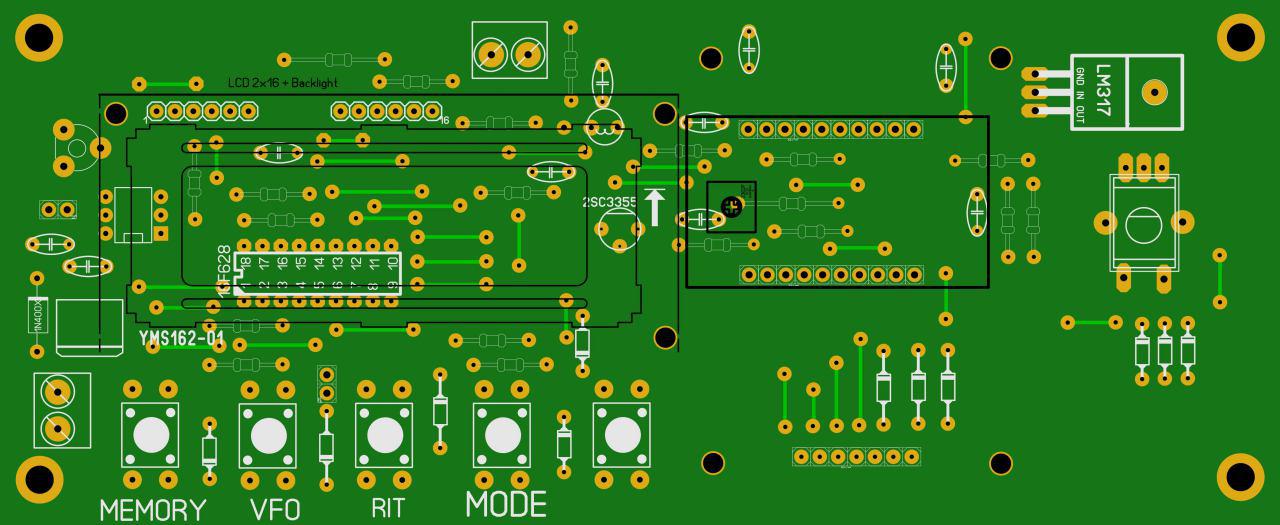
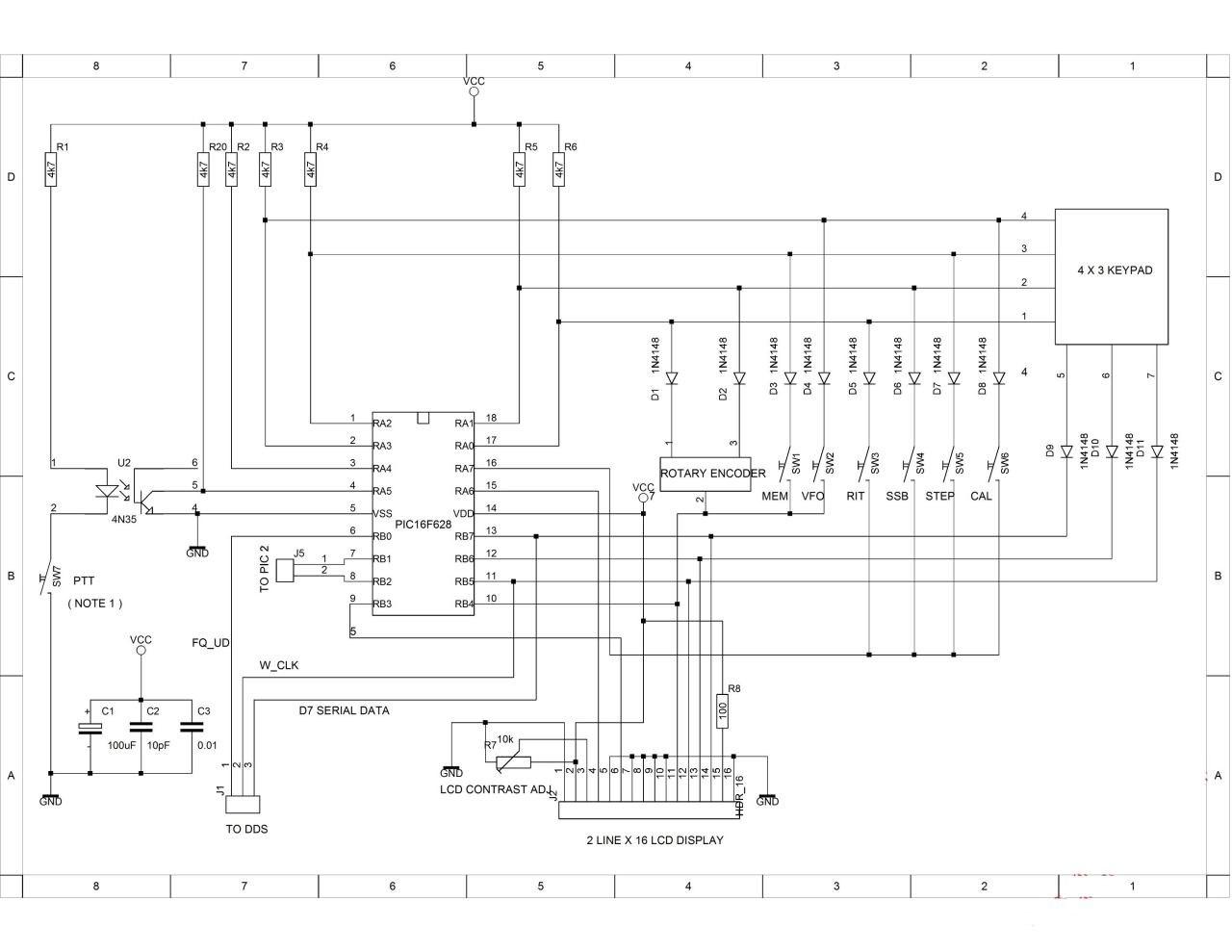
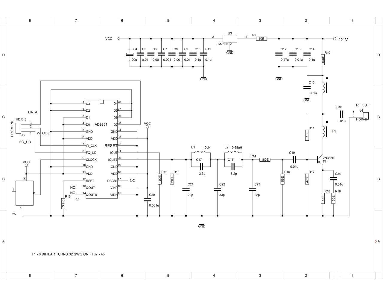
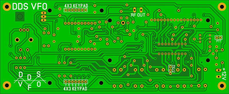
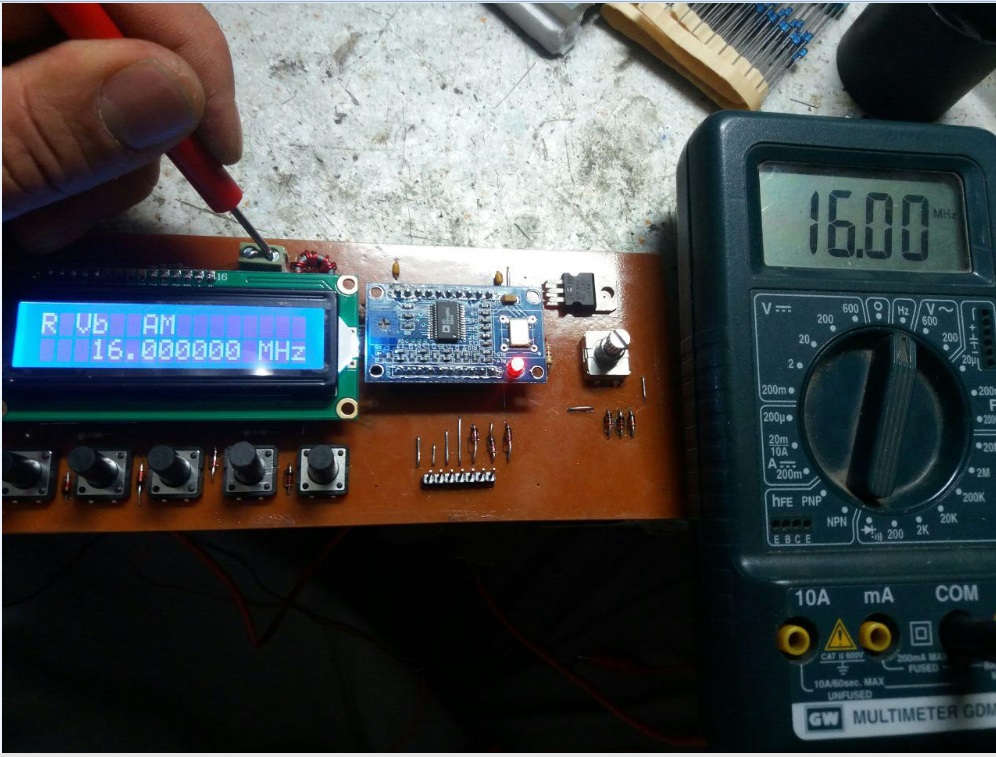
این طرح با استفاده از ماژول ۹۸۵۰ و مداربرنامه ریزی PIC تهیه شده و قادر است در دو اسیلاتور مستقل کار کند و دارای ۲۰ کانال حافظه کامل می باشد می تواند علاوه بر تهیه فرکانس مستقل در هر نوسانساز فرکانس میانی را اضافه یا کم نموده لذا در حالیکه اسیلاتور روی فرکانس محلی نوسان می کند فرکانس کار رادیو را نشان دهد که حاصل جمع یا تفریق فرکانس میانی و نوسان ساز محلی است دارای دکمه تنظیم دقیق بمقدار + - ۳کیلوهرتز می باشد مقدار دقیق اختلاف فرکانس ها در حالت کارکرد آ ام و تلگرافی و یو اس بی و ال اس بی در ان درنظر گرفته شده و قابل انتخاب است ورودی مدار با ولتاژ۱۲ ولت است می توان با استفاده از نوسانساز دوم فرکانس فرستنده و گیرنده را مجزا انتخاب کرد
علاقمندان جهت اظهار نظر یا سفارش و تهیه این دستگاه با ایمیل مهندس رسولی با ادرس زیر تماس حاصل فرمایند:
Jfrras@gmail.com
باسلام
بررسي بسيار جالب بالونها و رفتارشان در وبلاگ عزيز دوستم جناب اقاي فرزاد از المان
http://etesalkootah.blog.ir/1395/02/08/BalUn_Understand_make_Measure_Part_6
.
بالون هیبریدی: ترکیب بالون ولتاژ و بالون جریان
نکات مهم در بالون های هیبریدی عبارتند از:
.

.
یک بالون ولتاژ و یک بالون جریان به صورت متوالی (سری) بسته می شوند،
- هر یک از این بالون ها کار خود را به بهترین نحو انجام می دهد و اگر از وظیفه ی یکی چیزی باقی بماند، دیگری انجام آن را به عهده می گیرد.
- بالون ولتاژ، مستقل از امپدانس آن، ولتاژ روی بار را متعادل می کند. این بالون در اغلب موارد وظیفه ی یک ترانس تطبیق را هم به عهده می گیرد و امپدانس را تبدیل می کند.
- بالون جریان 1:1 برای امپدانس های نامعین، به عنوان یک چوک مسدودکننده ی نامتعادل، از بالون ولتاژ در مقابل جریان های نامتعادل بر روی خط انتقال (فیدر) محافظت می کند.
- بالون ولتاژ و بالون جریان، هر کدام بر روی یک هسته ی مجزا پیچیده می شود. به این ترتیب از بروز تاثیرات متقابل به واسطه ی فلوی مغناتیسی پیش گیری می شود.
.
بالون با رفتار مبدّل و نسبت تبدیل امپدانس (بالون هیبرید)
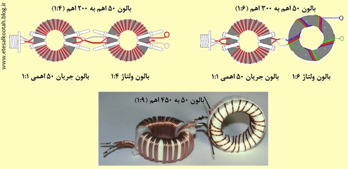
ساختن یک «بالونِ مبدل» با نسبت تبدیل امپدانس (مثلاً 1:4 ، 1:6 ، 1:9) که همزمان بتواند جریان های غلافی را نیز تضعیف کند، مستلزم به کار گیری دو هسته است.
.
.
این هدف با ترکیب یک «بالون نامتعادل/نامتعادل» (UnUn) یا یک «بالون ولتاژ» به عنوان مبدّل امپدانس، سری با یک «بالون جریان» به عنوان چوک مسدود کننده (مجموعاً: بالون هیبرید) حاصل می شود. به عبارت دیگر:
یک هسته برای بالون جریان – یک هسته ی جداگانه برای مبدل با باند پهن.
- مبدل امپدانس با باند پهن برای نسبت تبدیل مورد نظر،
- بالون جریان 1:1 که جریان نامتعادل را سرکوب می کند.
کاربردهای این نوع بالون ها، به عنوان مثال، عبارتند از:
- در مسیر فرستنده - کابل هم محور (کواکسیال) - بالون: «لوپ تمام موج» ،
- در مسیر فرستنده - کابل هم محور - بالون: دایپل چندبانده،
- در مسیر فرستنده - کابل هم محور - بالون: آنتن تجمیع جریان (Current Sum Antenna) ،
- در مسیر فرستنده - کابل هم محور - بالون: Windom Antenna ،
- در مسیر فرستنده - کابل هم محور - بالون: آنتن سیمی از نوع سیم دراز Long Wire .
.
بالون هیبریدی بر اساس طراحی«ویپرمن»
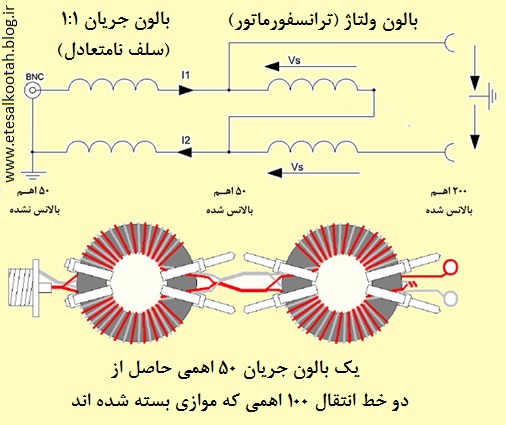
این بالون بر اساس طراحی رادیوآماتور، آقای «ویپرمن» (Wipperman) با شناسه ی آماتوری DG0SA ساخته می شود و در آن «بالون جریان» در سمت 50 اهمی قرار می گیرد.
.
.
بالون هیبریدی بر اساس طراحی«رُز»
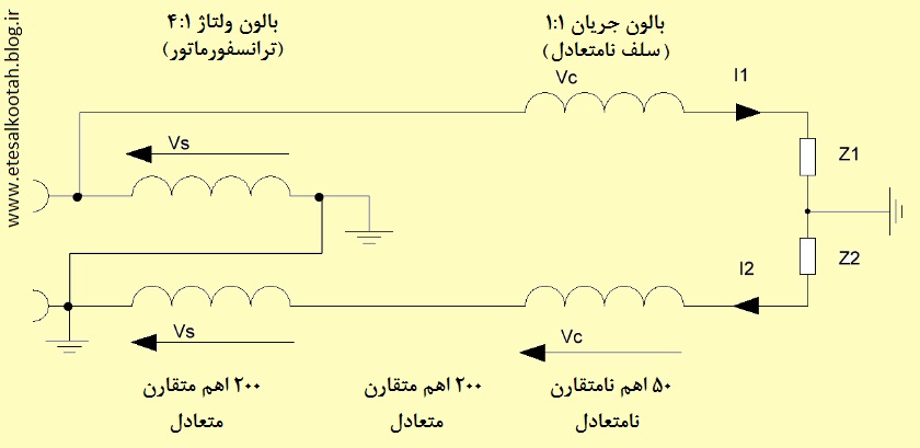
این بالون بر اساس طراحی رادیوآماتور، آقای «رُز» (Roos) با شناسه ی آماتوری ZS1AN ساخته می شود و در آن «بالون جریان» در سمت 200 اهمی قرار می گیرد.
.
.
بالون هیبریدی 2/25: 1
در اینجا از یک بالون ولتاژ، که به صورت «اتوترانسفورماتور» برای تبدیل امپدانس مداربندی شده، و یک بالون جریان برای متقارن کردن آن استفاده شده است. اتوترانسفورماتور در بر دارنده ی سه پیچش متوالی (سری) است.
.
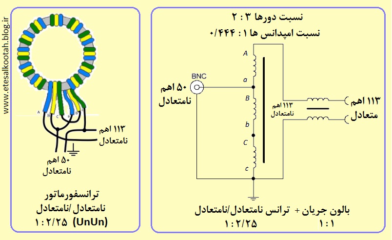
.
نرخ تبدیل امپدانس در اتوترانسفورماتور به صورت 2 به 3 است یعنی در حالی که خروجی 113 اهمی به اولین و آخرین پایانه های سری پیچش ها وصل شده (سه سوم = 1)، ورودی 50 اهمی در مدار دو تا از پیچش ها (دو سوّم) قرار داده شده است.
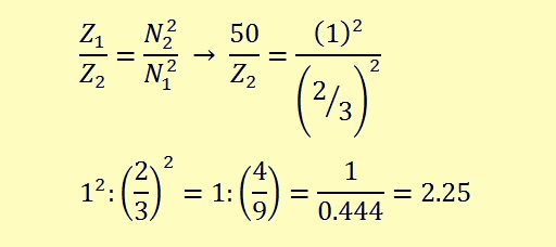
می دانیم که در ترانسفورماتورها نسبت امپدانس های اولیه و ثانویه با عکس مربع دورهای اولیه و ثانویه متناسب است. بنابراین، خواهیم داشت:
.
.
و از اینجا درمی یابیم که امپدانس خروجی این بالون 2/25 برابر ورودی، یعنی در حدود 113 اهم است.
.
آشنایی با بالون های فشرده – سری AMA
شرکت آلمانی «هوفی» (Hofi) در سبد تولیدات خود سری بالون های کمپکتی با نام تجارتی «فریتسل» (Fritzel) با تیپ «آ.ام.آ.» دارد. در این محصولات هر دو بالون های ولتاژ و جریان دور یک هسته ی فریت پیچیده شده اند. برخی از رادیوآماتورها این محصولات را نمی پسندند و به عنوان یک تولید اشتباهی از آن یاد می کنند. در اینجا ما با یکی از آنها با مدل AMA2 و دلایل مخالفان آن آشنا می شویم:
.
![بالون هیبریدی فشرده-بالون جریان و ترانس تبدیل امپدانس روی یک هسته ی فریت پیچیده شده اند بالون هیبریدی فشرده-بالون جریان و ترانس تبدیل امپدانس روی یک هسته ی فریت پیچیده شده اند]()
.
همان طور که در تصویر دیده می شود، این بالون شامل یک ترانس تبدیل امپدانس 1:2 و یک بالون جریان 1:1 است. بالون اخیر از دو رشته سیم لاکی تابیده شده تشکیل یافته که دور همان هسته ی ترانس تبدیل پیچیده شده است.
به عقیده ی نویسنده، بر روی بالون جریان، فلوی مغناتیسی که توسط ترانس ایجاد می شود، اثر می گذارد و در نتیجه انرژی نامتقارن از طریق فلوی مغناتیسی در بالون جریان القا می شود. به این ترتیب، بالون جریان در این مجموعه فایده ای نخواهد داشت.
علاوه بر این، نحوه ی ساخت این بالون (استفاده از سیم لاکی با عایق معمولی) آن را در مقابل ولتاژهای بالا آسیب پذیر می سازد.
محصولات این تولیدکننده را در نشانی www.hofi.de ملاحظه خواهید کرد.
.
ادامه دارد ...
.
.
مطالب مرتبط:
بـالـون: شناخت، ساخت، سنجش -5
بـالـون: شناخت، ساخت، سنجش -4
بـالـون: شناخت، ساخت، سنجش -3
بـالـون: شناخت، ساخت، سنجش -2
بـالـون: شناخت، ساخت، سنجش -1
.
برگرفته از سایت etesalkootah.blog.ir
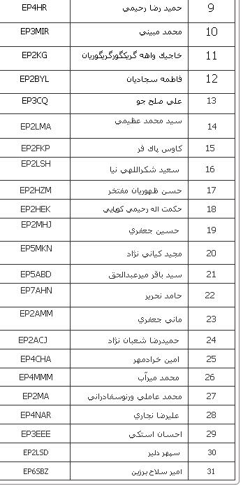
با سلام
مطلب فوق جهت اطلاع از اثر فاصله از زمين انتن برحسب طول موج به عرض مي رسد
ضمن تشكر از جناب مهندس مثيمي استاد بزرگوار خودم
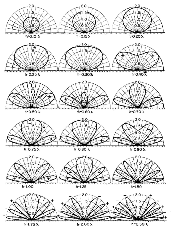
http://ham.stackexchange.com/questions/484/what-causes-ground-losses-in-a-hf-antenna-system
با سلام اعضاي گروه راديو اماتوري فوق از اكراين و ليتواني امشب وارد ايران شده و در شمال فعال خواهند بود
جهت تماس با اين گروه با شماره هاي ذيل تماس حاصل فرماييد:
سلام دوستان
روز همه بخیر
دوستانی که علاقه مند بازدید dxpedition در محل زیبا کنار هستند
با یکی از شماره های
09122613010
09123042161
09359500001
هماهنگ بفرمایند
http://www.lral.lv/exped/ep2a/index.html
دوستان عزیز DXpedition با شناسه EP2A با شرکت 7 نفر از کشور لاتویا و اوکراین از مورخه ۲۸ فروردین ماه بمدت ۱۰ روز در حوالی شهر انزلی برگزار میگردد.با توجه به اینکه برگزاری این رویداد موقعیت مناسبی جهت افزایش دانش فنی و عملی علاقمندان و رادیو اماتور های عزیز باشد لذا خواهشمند است در صورت تمایل با هماهنگی قبلی از این کمپ رادیویی بازدید فرمایید.


Written by Hans Summers
Wednesday, 06 April 2011 11:03
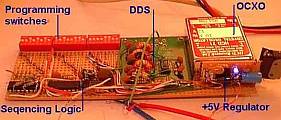
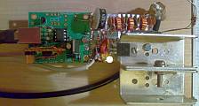
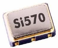
The Si570 is a relatively new device made by Silicon Labs. It's a very small device containing a crystal reference oscillator, digital Phase Locked Loop (PLL), and I2C interface so it can be programmed for any frequency between 10MHz and 945MHz (selected frequencies to 1.4GHz). Direct Digital Synthesis (DDS) chips such as those from the market leader Analog Devices have been around for longer. They are very different kinds of parts, even though they are both oscillators. Accordingly the best choice depends heavily on the application. These are my opinions about the relative advantages and disadvantages which may be important factors for your decision.
Projects
Experimental DDS project Si570-based QRSS transmitter
Reference data
Analog Devices DDS page
Analog Devices AD9910 DDS datasheet
Analog Devices AD9912 DDS datasheet
Silicon Labs
Si570 datasheet
Ease of Construction
Package comparison (not to comparable scale):
AD9910 DDS (QFP100) Si570 (7 x 5mm package)
The Si570 wins here. It has 8 pins, and although a small surface mount package, you can still solder it reasonably easily, even with no PCB. On the other hand, all of the modern DDS devices are in surface mount packages only, for example this 100-pin AD9910 DDS. Soldering that one ugly-style would be a challenge. Even the earlier generation DDS's with 28 pin SMD's weren't easy.
Output waveform
The Si570 has a squarewave output. Often that's fine, for example, if you want to drive a mixer with it: many mixers operate best when the VFO is a squarewave. If you want a sinewave, you'll need a lot of low pass filtering to get rid of the rich suite of harmonics.
DDS chips have a sinewave output: it is generated by the rapid output of a succession of analogue voltages via a Digital-to-Analogue converter (DAC), which approximates a sinewave. Many of the DDS chips have an onboard comparator which can easily be used to turn the sinewave output into a squarewave, if that's what you need. Bear in mind though that you need an anti-alias low pass filter on the output of DDS chips to produce a clean output.
Which one wins... depends on your application. If you only need a squarewave, Si570 is fine. DDS can do either (if it is one of the ones which has a comparator on board), so for that reason, my winner is DDS.
Frequency range
A DDS will function right down to near DC. The practical upper range of a DDS is normally considered limited to 40% of its reference clock oscillator. This is a limitation of the digital synthesis of the waveform, which is a sampled process (look up Nyquist). Frequencies higher than 40% of the reference clock oscillator are also possible at the output of the DAC which is unfiltered, and these could be extracted by suitable bandpass filtering instead of the usual low-pass filter. Outputs like this require more detailed design and the performance is unlikely to be as good.
By contrast the Si570 allows any output frequency from 10MHz to 945MHz, and a more limited selection of frequencies all the way up to 1.4GHz. I have heard that operation below the specified 10MHz lower limit is possible too but have not confirmed this myself.
Here I'd say the DDS would win if you wanted to be able to go down to very low frequencies, but the Si570 would win if your application needs very high frequencies, or a very wide continuous range up to UHF and beyond. But because the Si570 has such a large and convenient range, let's call it the winner.
Frequency stability/accuracy
DDS requires a reference clock oscillator, which one normally provides with a high stability crystal oscillator. You have to provide the crystal reference oscillator. You can make it as accurate and stable as you like. GPS-lock it, lock it to a Rubidium standard, put it in a constant-temperature oven... whatever you like.
The Si570 has its own crystal oscillator built in. The difference here is that you have not much control over the internal oscillator of the Si570. You can't adjust it to be exactly on frequency, you can't lock it to a frequency standard or GPS reference. (It does have some frequency adjustment via an ADC input, but you'd still need to measure the actual frequency, compare it to a standard, and estimate a correction voltage - so it doesn't really do the job except with extreme effort). In my Si570-controlled QRSS beacon I found that the Si570 was already quite accurate and stable: A few Hz off frequency at 10.140MHz and it did not seem to drift perceptibly with room temperature variations, though neither of these measurements were detailed.
In my opinion, if you need stability and accuracy, DDS wins here, because you can make it as accurate and stable as you like.
Frequency agility
The frequency of a DDS can be set almost instantly (at least, as fast as you can clock your new desired frequency into the chip)! Most DDS chips have at least 32-bit tuning word resolution, and some of them even have 48-bit tuning word (e.g. AD9912) giving you tuning resolution down to steps of a few micro-Hz, if you should ever need it!
Si570's can also be tuned in very small steps but the frequency does not change instantly. When you make a change in frequency, there is a delay of up to 10ms (0.01s) while the internal PLL locks on to the new frequency. That can sound like a small click/chirp in your receiver audio for example, if you are using the Si570 as your receiver VFO. The Si570 can also be tuned much faster (100 times faster) for small steps within 3,500 parts per million (ppm) of the centre frequency. In this case, the settling time is less than 0.1ms (100us).
This delayed tuning of the Si570 might make it unsuitable for some applications, e.g. digital communications modes where the frequency must be changed quickly, or split frequency operation, or perhaps QSK CW with an offset between receive and transmit (though this would be unlikely to exceed the 3,500 ppm needed for a large-step).
So for frequency agility, the DDS definitely wins if your application needs it: frequency changes are as good as instant!
Programming interface
The DDS chips have a serial programming interface, and programming is easy. Some also support a parallel programming interface (one byte at a time). I built a DDS generator which can be done without a micro-controller at all (see here) but normally you'd be using a microcontroller.
The Si570 has an I2C interface, and programming the frequency you want is a little more tricky - involving some calculation of different multiplier/divider values and the internal digitally-controlled-oscillator frequency. A little more complex than the DDS programming word, which is a simple fraction of the reference clock frequency.
The Si570 is still not a problem if you're reasonably competent with programming microcontrollers, but as the DDS is more straightforward it has the lead here, I think.
Performance: Spurs
The Si570 is a digital phase locked loop oscillator producing a squarewave output. As all squarewaves, this is a fundamental plus a rich comb of odd harmonics. If a sinewave is required and the range of operation is narrow, the spurs can be filtered out if required, and are of course a reasonable distance from the carrier (i.e. at 3, 5, 7... times the fundamental carrier frequency). There is some harmonic content on even harmonics too as the output is not guaranteed to be a perfect 50% square wave. Other spurious responses are very low for the Si570 and not normally considered to be a problem.
DDS chips have a bad reputation for spurs! This is because the output sine waveform is approximated by a series of discrete steps, which are later filtered external to the chip by your low pass filter. The process is inherently a discrete appoximation of the ideal sinewave, which generates spurious responses. The spurii are numerous and at various different amplitudes, and also can occur very close to the carrier, so you cannot filter them all away.
Some of the most modern Analog DDS chips include a "SpurKiller" technology, such as the AD9912 with two SpurKiller channels. These are effectively two parallel DDS cores, whose frequency and output amplitude and phase can be set up such that if your application can predict or measure the location of your spurs, you could choose your two most objectionable spurs, and eliminate them by cancelling them out. I think the range of instances that this would be useful would be somewhat limited. The datasheet mentions that this feature performs optimally slightly differently on each device, which would further limit its usefulness in many practical applications.
The seriousness of the spurs problem depends mainly on two factors: the resolution of the DAC and the proportion of the output frequency relative to the reference oscillator frequency. DAC's typically go from 10-bits in some earlier devices up to 14-bits in a top-of-the-range device like the AD9912. A higher resolution DAC produces less spurs. Similarly if the reference oscillator frequency is very high relative to the output frequency, spurs are reduced. The AD9912 can operate with up to a 1GHz reference oscillator. For output frequencies in the 0-30MHz HF range, the spurs are very minimal. For VHF or UHF output frequencies the spurs could be more objectionable for sure. For amateur radio use, even on a low-end DDS, spurs are unlikely to be a problem in purely transmit applications, because they are less than the legal spurious output limits of amateur radio equipment. In receive applications, spurs will show up as birdies in the receiver, and are more serious. However, for an HF receiver if you were using a modern DDS such as the AD9912 with 1GHz reference clock oscillator, then the spurious content would be very low and unlikely to be noticeable in most cases.
A high-end DDS with careful design hasn't got spurious response problems under a limited range of circumstances i.e. at HF. But the Si570 wins on this one because it doesn't have spurs problems anyway.
Performance: Phase noise
Phase noise can be imagined as a widening of the theoretical perfect vertical line you would see on a spectrum analyser examining the output signal. One reason why it is important in a receiver, is that it mixes with strong signals some kHz away from your wanted signal to produce an elevated noise floor, which could easily obscure a weak signal you want to listen to. For a high performance receiver, it is really important to use a low phase noise local oscillator.
The phase noise performance of DDS is generally very good. There is a little jitter added by the imperfections inherent in the digital waveform approximation and some general very limited phase noise added by the imperfections of this digital device. Also the DDS phase noise can only ever be as good (actually slightly worse) than the reference clock oscillator. Typically this would be a crystal-based crystal oscillator, and crystals, being very high Q devices, have very good phase noise performance. So generally, DDS is considered a low phase-noise technology.
Many of the DDS chips include a reference clock multiplier PLL. This can be used to provide an internal very high frequency reference clock, up to the rating of the device e.g. 1GHz for the AD9910, from a much lower input clock oscillator frequency. Remember that high reference clocks are best, for best spur performance, so the multiplier can be useful in that regard. It can simplify your design greatly, but it comes at the price of adding unwanted phase noise in the internal PLL multiplication process. Frequency multiplication in any event carries a theoretical minimum 6dB/octave (or 20dB/decade) phase noise penalty, but if you use the internal PLL multiplier you add even more than this. So for best phase noise performance, leave the PLL switched off and build your own external high frequency reference oscillator.
The Si570 is based on a PLL technology, which generally has a much higher phase noise. However in the Si570, they minimise the phase noise by careful design and by using a very narrow loop bandwidth. This is the reason why it has a relatively slow settling time (10ms) when you change the frequency. So the phase noise of the Si570 is pretty respectable, and will probably be adequate for many applications.
How about a comparison between DDS and Si570? The phase noise performance data in some of the DDS datasheets is somewhat limited. Often they show the "residual phase noise", which means the additional phase noise which is added to that of the reference oscillator by the DDS process itself. This is not the same as the actual phase noise you would observe on the output - for that you need to also add the phase noise of the reference oscillator - so it is not directly comparable with the phase noise of an Si570. However, some of the DDS device datasheets show an absolute phase noise chart, and an example of this is the AD9912 which shows output phase noise for various output frequencies and assuming the use of a high performance 1GHz Wenzel oscillator. The Si570 datasheet has a table of phase noise at three output frequencies (120MHz, 156.25MHz, 622.08MHz).
It is important to remember that when a frequency is divided, the phase noise also decreases by 6dB per octave (or, 20dB per decade). So in any comparison, we need to take this into account if the frequencies concerned are not the same. For this example comparison, I am choosing to compare the Si570 data at 156.25MHz with a graph in the AD9912 datasheet at 171MHz. Strictly I should adjust for this frequency difference (i.e. 156.25MHz and 171MHz) by doing some mathematics for the 6dB/octave. However they are close enough frequencies that this would make only 1dB difference or so, which in any event is only about the precision I can read off the values from the chart in the AD9912 datasheet, so I'm going to ignore it for now. This small inaccuracy would act in favour of the Si570 which is at the lower frequency in this comparison.
So, here's a table of the values for 156.25MHz from the Si570 datasheet, and the corresponding values read off the graph from the AD9912 datasheet. These results would be expected to be broadly repeatable with the two devices at other frequencies, appropriately scaled by 6dB/octave (20dB/decade). The units of phase noise are dBc/Hz.
Offset Si570 AD9912
100Hz -105 -125
1kHz -122 -138
10kHz -128 -148
100kHz -135 -157
1MHz -144 -162
10MHz -147 -163
Here are those same results, represented on a graph:
The overall conclusion here has to be that a top-end DDS with quality reference clock oscillator and good design (the AD9912 at 1GHz refclk), can outperform the Si570 by 20dBc/Hz. However, I'd say that for many applications the Si570 phase noise performance would be sufficient, and probably better than many expensive commercial "black box" amateur radio transceivers on the market.
But due to the excellent phase noise performance of DDS technology, DDS is the winner here.
Power Consumption
Neither the Si570 nor DDS are exactly innocent when it comes to power consumption. Both will be agressively trying to drain your batteries, if you are operating battery-powered equipment.
The Si570 is stated to consume 120mA at 3.3V for the LVPECL, which is 396mW. An AD9912 on the other hand, requires separate voltages at 1.8V and 3.3V for its various sections (analogue and digital). Each has different current consumption, but the datasheet also lists typical power consumptions under various configurations. The power consumption is between 637mW and 747mW. The AD9912 even has an exposed copper pad on the bottom to help get the heat out! Don't forget, this is even before you consider that the Si570 has its own internal reference clock oscillator, whereas DDS chips needs you to provide one externally, which will add even more power.
Some of the older, less powerful DDS chips do consume less power. But as I've mentioned the top of the range DDS devices a lot, particularly the AD9912, I'll say that the Si570 wins on this measure.
Cost
Neither are cheap. The Si570 is a similar price to some of the lower-end DDS chips but for a high-end DDS such as the AD9910 or the AD9912 I keep mentioning, you'll be paying considerably more than for the Si570. Also the DDS require more support circuits such as the reference clock oscillator, which is also unlikely to be cheap. On the other hand, if you're a cunning (and stingy) radio amateur, you used to be able to get free DDS samples from Analog. You never could get free Si570 samples from SiLabs. Overall I think we have to say the Si570 wins on cost, generally.
Other features
The Si570 is just a plain oscillator. If you want more features, you want a DDS! Read the datasheets, and be amazed! Control the amplitude, control the phase, add spur killing. Some DDS devices contain TWO cores and outputs, which can be set to be offset at 90-degree phases (useful for phasing direct conversion mixers for example - check out the AD9854). Automate your amplitude modulation, frequency modulation, phase modulation, automatic sweep, and other kinds of features I can't even remember or understand. You probably don't need them, they're probably just sales gimmicks, but on features you have to agree, the DDS is definitely the winner.
Overall complexity
An Si570 is pretty simple to use. Just add a 3.3V power supply, connect up your microcontroller, and you're ready to go.
Not so, the DDS! With a DDS you may need four separate well-regulated and clean power supplies, some at 1.8V and some at 3.3V. You need a reference clock oscillator. Some DDS chips have an onboard oscillator where you can just connect the crystal directly to the chip. But for best performance you'll want to design and build a 1GHz oscillator, which is no trivial matter, and get that properly coupled into the chip input. Then you need the reconstruction filter (typically low pass) at the output, and that needs to be carefully designed too. The board design needs lots of care too, with all that high frequency stuff rolling around.
Yes, using a DDS is a lot more effort than an Si570. So on complexity, the Si570 is definitely the winner.
Summary
So after all that, here's my summary of my opinion on the various criteria by which to judge these two kinds of oscillator. Bear in mind that every application is different! In some applications, some of these criteria don't matter to you at all, or the decision of what is better will be clear (and opposite to my conclusion). In others, you are faced with the usual decisions about trade-offs. Performance and complexity; features and cost; etc. But I'll generalise and operate in typically bi-polar manner and give my overall winner in every category regardless, and leave the judging of your applications to you.
Category Winner
Ease of construction
Si570
Output waveform DDS
Frequency range Si570
Frequency stability/accuracy DDS
Frequency agility DDS
Programming interface DDS
Performance: Spurs Si570
Performance: Phase noise DDS
Power Consumption Si570
Cost Si570
Other features DDS
Overall Complexity Si570
Further reading
For a great inspiring read about a wonderful ultimate-high-performance receiver project, and the reasons why Martein PA3AKE chose the AD9910 DDS for his oscillator, please visit his site. For Si570 kits see SDR Kits. There are loads of DDS kits around, just google for them. For lots of interesting info and discussion about the Si570, visit Andy G4OEP's Si570 pages; like Martein PA3AKE, Andy never does anything by halves.
My Favourite
What's best really depends on the application. But if you're still reading this, and I have to choose a general overall favourite, I just have to choose the DDS. Just like a favourite colour, or a favourite lucky number, I don't need a good reason. I just LIKE it better!
Last Updated on Monday, 03 March 2014 04:54
در این مقاله به معرفی یک مدار فرکانس شمار با محدوده ی کار تا 30 مگاهرتز و دقت 100 هرتز می پردازیم که دستگاه اندازه گیری ساده و کارآمدی برای کارگاه شما خواهد بود. این فرکانس شمار در اصل برای استفاده در یک دستگاه گیرنده-فرستنده ی رادیوآماتوری موج کوتاه طراحی شده بود، به این خاطر در ادامه ی شرح این فرکانس متر (که برای فرستنده-گیرنده ی پیش گفته طراحی شده بوده) با قابلیت ها و فانکشن هایی روبرو می شوید که ممکن است مورد استفاده ای در اندازه گیری های شما نداشته باشند که شما می توانید آنها را نادیده بگیرید.
با ارایه ی این مقاله، همزمان، به وعده ای که در مقاله ی «ساخت یک دستگاه آنالایزر آنتن» داده بودیم عمل می کنیم و مدار یک فرکانس شمار مناسب برای آن پروژه را در اختیار خواننده قرار می دهیم.
روشن است که از این فرکانس شمار به عنوان یک دستگاه مستقل نیز می توان استفاده نمود و ساختن و در دسترس داشتن چنین وسیله ی اندازه گیری مفیدی همواره به هر دوستدار الکترونیک خدمت خواهد کرد.
قلب این مدار یک میکروکنترلر PIC است که با قیمت مناسبی تهیه می شود. به این آی.سی. تعدادی افزاره ی معمولی دیگر و یک نمایشگر ال.سی.دی. دارای یک سطر 16 کارآکتری اضافه می شود. در حقیقت آرزوی داشتن فرکانس شماری ساده تر از این آرزوی محالی بیش نیست!
.
نقشه شماتیک مدار فرکانس شمار
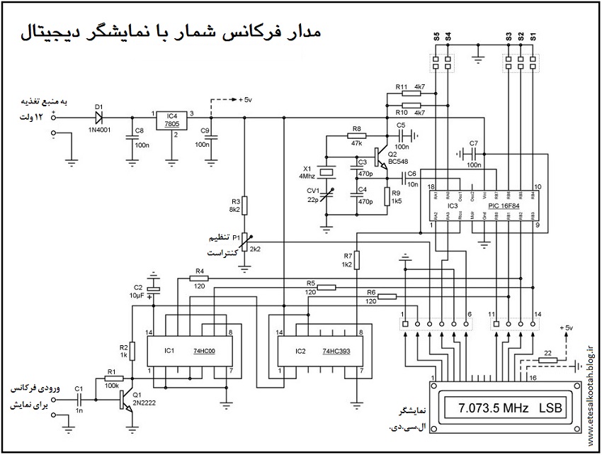
نقشه ی شماتیک مدار
.
همچنین باید یادآور شد که دقت نمایش این فرکانس شمار 100 هرتز است که برای کاربردهای معمولی بیش از حد دقیق محسوب می شود.
در مدار این فرکانس شمار نکته ی تازه ای دیده نمی شود و در طراحی آن از روش های معمول استفاده کرده ایم. برنامه ی میکروکنترلر را یکی از دوستانم، که با این افزاره ها آشناست، بازنویسی کرد تا پایانه های Ra و Rb میکروکنترلر از یک طرف برای کاربرد در نمایش فرکانس تولید شده در مولد «آنالایزر آنتن» به عنوان عضوی از آن دستگاه، و از سوی دیگر برای کاربرد در اندازه گیری های متفرقه انطباق داشته باشد. برنامه را از اینجا دریافت کنید:
.
دریافت برنامه های مدار فرکانس شمار
دریافت
عنوان: 10MHZ.HEX دریافت
عنوان: 10MHZ.HEX دریافت
عنوان: 4MHZ.HEX
دریافت
عنوان: 4.915.HEX دریافت
عنوان: 8.9063MHZ.hex دریافت
عنوان: 10.7MHZ.HEX
.
شرح زیادی در خصوص نحوه ی کارکرد مدار نمی توان ارایه داد، زیرا تقریباً تمام کارها در داخل میکروکنترلر انجام می پذیرد. دو ویژگی این مدار اجازه می دهند تا بتوان از آن در اندازه گیری و نمایش فرکانس خروجی اغلب مولدهای فرکانس استفاده کرد: آرایش ورودی-خروجی های میکرو به دلخواه کاربر برای تطبیق دادن آن با حالت (مُـد) کاربرد در هر موردِ فرکانسی، و امکان تنظیم «نوسانگرهای فرکانس مبنا» به عنوان «فرکانس رفرنس» در طیف وسیعی از فرکانس ها برای استفاده در تنظیم فیلترهای کریستالی و جبران خطای کوارتزهای به کار رفته در آنها.
بیایید نگاهی به موضوع « آرایش فرکانس ورودی-خروجی» بیاندازیم:
- پایانه ی ورودی-خروجی RB6 (مرتبط با S3): در صورت وجود پل (جامپر) روی S3، همه ی ورودی-خروجی های دیگر غیرفعال می شوند. به عبارت دیگر، فقط همان فرکانس سنجیده شده نمایش داده می شود. در این حال می توان از آن در نمایش مستقیمِ فرکانس کار بخش های مختلف گیرنده ها و فرستنده ها استفاده کرد. در دستگاه «آنالایزر آنتن» ما هم این فرکانس شمار را در این «مُـد» با یک تکه کابل هم محور (کواکسیال) کوتاه به آن متصل می کنیم. در اندازه گیری مثلاً فرکانس IF یک گیرنده، فرکانس شمار را از طریق یک خازن 3/3 تا 47 پیکوفاراد به دستگاه تحت آزمایش وصل کنید تا میان دو مدار جداسازی DC اجرا شود. پس از آن می توان تنظیمات ضروری احتمالی را در گیرنده انجام داد.
اما اگر پل روی S3 را برداریم، همه ی ورودی-خروجی های میکرو فعال خواهند شد. این حالت کاری برای مواقعی مانند استفاده از فرکانس شمار در یک مدار مرّکب گیرنده-فرستنده با ساختمان سوپرهترودین (تبدیل فرکانس) و وجود فرکانس ها و فرکانس سازهای متعدد مناسب است.
- پایانه ی ورودی-خروجی RB5 (مرتبط با S2): وقتی پل بر آن قرار گیرد، فرکانس یک نوسانگر بیرونی (مثلاً یک VFO) با مقدار فرکانس اندازه گیری شده جمع می شود. با برداشتن پل، فرکانس نوسانگر بیرونی از مقدار فرکانس اندازه گیری شده کم می شود. این فانکشن ها در اندازه گیری طبقات فرکانس میانی دستگاه های فرستنده-گیرنده کاربرد دارد و استفاده از آنها در دستگاه «آنالایزر آنتن» لزومی ندارند.
- پایانه ی ورودی-خروجی RB4 (مرتبط با S1): اصلاح مقدار نمایش به اندازه ی باضافه یا منهای 1/5 کیلوهرتز برای رفتن به باند جانبی بالا یا پایین برای نشان دادن حالت های کارکرد «تک باند جانبی» (SSB) یا «موج پیوسته» (CW). اگر پل بر روی S1 قرار گیرد، اصلاح معادل 1/5- کیلوهرتز (باند جانبی پایین LSB)، و اگر برداشته شود، برابر 1/5+ کیلوهرتز (باند جانبی بالا USB) خواهد بود.
- پایانه ی ورودی-خروجی RB0 (مرتبط با S4 ): با قرار گرفتن پل روی S4، نمایشگر مقدار مجموع فرکانس کار و عبارت USB به معنی «باند جانبی بالا» را نشان خواهد داد.
- پایانه ی ورودی-خروجی RB1 (مرتبط با S5 ): با قرار گرفتن پل روی S5، مانند بالا علاوه بر فرکانس کار، عبارت LSB نیز نمایش داده خواهد شد.
- با قرار دادن پل رو هر دو پایانه ی RA0 و RA1: عبارت CW که همان حالت ارسال «تلگرافی» است بر صفحه ی نمایش ظاهر خواهد شد.
مزیت وجود این پل ها در آن است که امکان اتصال فرکانس شمار را به عنوان دستگاه جانبی (Periphery) به رایانه می دهد. لازم به یادآوری نیست که تمام پایانه های میکروکنترلر را می توان به واسطه ی ترانزیستور و یا اُپتوکوپلر تحت کنترل و فرمان الکترونیکی نیز قرار داد. این امکان در طراحی و ساخت دستگاه های پیچیده تر بسیار مطلوب است.
میکروکنترلرها معمولاً در داخل خودشان «نوسانگر مبنای زمان» (Time base oscillator) دارند، طوری که مثلاً برای راه انداختن نوسانگرِ 16F84 فقط لازم است بین پایانه های 15 و 16 آن یک کریستال کوارتز به همراه دو خازن کوچک (برای تنظیم دقیق فرکانس) نصب کرد. اگر دستگاه فرکانس متر برای استفاده در یک دستگاه تجارتی در نظر گرفته شده باشد، مشکلی در استفاده از این نوسانگر داخلی در پیش نخواهد بود، اما اگر قرار است فرکانس شمار شما در دستگاه دقیق تری مورد استفاده قرار گیرد، نباید در قسمت نوسانگرِ میکرو از کوارتزهای خیلی ارزان محصول تولیدکنندگان ناشناس استفاده کنید. نمونه ی چنین کاربردهایی در امور رادیوآماتوری ساخت فیلترهای کریستالی باند باریک است.
تفاوت میان مشخصه های کریستال های کوارتز موجود در بازار بر حسب سازنده بسیار زیاد است. من خودم در میان وسایلم تعدادی کریستال 10 مگاهرتز دارم که برخی از آنها دقیقاً 10 مگاهرتز هستند، اما بخشی نیز حتی خطای «آفسِت»ی تا 9/997 مگاهرتز دارند (بسته به این که برای تشدید سری یا موازی ساخته شده باشند، که البته روی آنها درج نشده است!). باید دانست که در میکروکنترلرها اصلاح حدّی از انحرافِ فرکانس، که مقدار آن از یک کیلوهرتز بیش تر باشد، با اضافه کردن خازن تریمر هم ممکن نخواهد بود. البته امکان اصلاح نرم افزاری وجود دارد که این راه حل برای یک کار غیرحرفه ای بسیار دشوار است. راه دیگر برای حذف اثر خطای انحراف فرکانس، بالا بردن فرکانس مبنای زمانی تا حد ممکن است.
در هر صورت ما در طراحی خود راه حل ساخت نوسانگر بیرونی، بیرون از میکرو، را انتخاب کردیم. در مدار ما که پیرامون Q2 ساخته شده، به کمک خازن CV1 می توان به جبران انحراف فرکانسی تا 4 کیلوهرتز دست یافت.
نمایشگر LCD به کار رفته در مدار از نوع ساده و معمولی است که داری یک سطر و 16 کارآکتر می باشد که برای کاربرد ما کاملاً کفایت می کند.
.
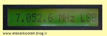
نمایشگر ال.سی.دی. و نمونه ای از نمابش آن
نمایشگر ال.سی.دی. و نمونه ای از آنچه که نشان می دهد
.
ارزان ترین نوع آن فاقد روشنایی بود، اما ما نوع دارای روشنایی پشتی (Back light) را انتخاب کردیم که اندکی گران تر بود، اما بسیار حرفه ای تر به نظر می رسد. من برای روشن کردن روشنایی ال.سی.دی. پایه ی 16 آن را به زمین و پایه ی 15 آن را از طریق یک مقاومت محدودکننده ی جریان به 5+ ولت (بعد از تثبیت کننده IC4) وصل کردم. توجه بفرمایید که آنچه در شماتیک مدار در داخل قسمت خط چین قرار دارد، روی فیبر مدار چاپی نصب نمی شود.
.
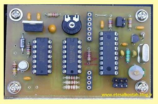
بورد مونتاژ شده ی مدار فرکانس شمار
.
مقدار اهمی این مقاومت باید طوری انتخاب شود که جریان گذرنده هیچگاه از 120 میلی آمپر بیش تر نشود. در بسیاری از موارد یک مقاومت 22 اهمی مناسب است. همچنین، در صورتی که از فرکانس شمار در یک وسیله ی قابل حمل و باتری خور استفاده می شود، خوب است که سر راه تغذیه ی روشنایی ال.سی.دی. یک کلید قرار دهید تا در مواقع غیرضروری بتوانید آن را خاموش و در مصرف باتری صرفه جویی کنید. توجه کنید که ال.سی.دی. با روشنایی 121/3 میلی آمپر و بی روشنایی فقط 1/3 میلی آمپر جریان می کشد!
پتانسیومتر P1 «کنتراست» یا درجه ی خاکستری نمایش کارآکترها را تنظیم می کند. اگر این پتانسیومتر درست تنظیم نشود، ممکن است هیچ کارآکتری روی نمایشگر دیده نشود، طوری که به نظر برسد دستگاه خاموش است و یا ال.سی.دی. خراب است!
ترانزیستور Q1 و افزاره های پیرامون اش یک تقویت کننده ی کوچک را شکل داده اند که سیگنال ورودی برای اندازه گیری را تا تراز ولتاژی لازم برای کار مطمئن در میکروکنترلر تقویت می کند. پایانه ی ورودی سیگنال به مدار را می توان به یک کانکتور فرکانس بالا (مثلاً از نوع SMA یا BNC) مجهز کرد. اما اگر ارتباط مستقیم مورد نظر است، باید از کابل هم محور (کواکسیال) استفاده شود. اگر این ارتباط کوتاه باشد، حتی می توان از کابل هم محور صوتی نیز برای این منظور استفاده نمود. در صورت قوی بودن سیگنال ورودی، می توان در مسیر آن یک مقاومت قرار داد. همچنین در مواردی که احتمال تداخل DC بین دو دستگاه و تاثیر منفی بر دامنه ی سیگنال نوسانگر وجود داشته باشد، باید در مسیر کابل، یک خازن سرامیک 3/3 تا 47 پیکوفاراد قرار داد.
دامنه ی سیگنالی که به فرکانس شمار ما وارد می شود باید کمینه 10 میلی ولت، و بهینه 40 میلی ولت باشد. اما دامنه ی این سیگنال هیچگاه نباید از 400 میلی ولت تجاوز کند.
.
طرح فیبر مدار چاپی و راهنمای چینش افزاره ها بر آن
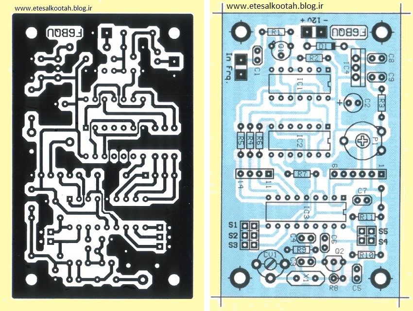
طرح فیبر مدار چاپی و راهنمای چینش افزاره ها بر آن. ابعاد واقعی فیبر 48×76 میلی متر است.
.
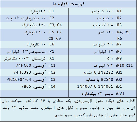
برای تنظیم فرکانس نوسانگر مدار به یک اسیلوسکوپ یا یک فرکانس شمار دقیق احتیاج است. تنظیم فرکانس با چرخاندن تریمر CV1 انجام می شود. اگر جوشن های خازن کاملاً همپوشانی پیدا کردند اما فرکانس همچنان انحراف داشت، باید یک خازن کوچک، در حدود 20 پیکوفاراد (یا در صورت لزوم با ظرفیتی بزرگ تر) را با تریمر موازی کنید تا به تنظیم صحیح برسید.
.
برگرفته از سایت etesalkootah.blog.ir
با سلام و تسليت ايام وفات بانوي دوعالم مادر سادات حضرت فاطمه زهرا (ع)
مطلبي از دوست و سرور عزيزم جناب مهندس فرزاد در وبلاگشون ديدم كه بسيار جالب بود و براي اطلاع دوستان عرضه مي شود
«مدولاسیون دلتا» (DM = Delta Modulation) روش ساده ای برای مدولاسیون برای دیجیتالی کردن سیگنال های آنالوگ است و نوع اصلاح شده ای از «مدولاسیون رمز پالسی» (PWM) است.
در مدولاسیون دلتا، از سیگنال آنالوگی که قرار است دیجیتالیزه شود، در فاصله های زمانی معیّن نمونه برداری می شود (تصویر 1) و مقدار این نمونه با نمونه ی برداشت شده ی پیشین مقایسه می شود.
.
فرآیند مدولاسیون و دمدولاسیون.
در صورتی که تفاوتی بین دو نمونه وجود نداشته باشد، تراز منطقی در خروجی مدولاتور بر وضعیت «سیگنال ساعت» (Clock) در لحظه ی نمونه برداری منطبق خواهد بود و اگر در این زمان سیگنال ساعت در تراز منطقی 1 باشد، خروجی مدولاتور هم در تراز 1 قرار خواهد داشت و اگر سیگنال ساعت در تراز منطقی صفر باشد، خروجی مدولاتور در تراز صفر واقع خواهد شد.
حال، اگر نمونه ی جدید نسبت به نمونه ی پیش از آن مثبت باشد، یک 1 منطقی در خروجی مدولاتور ظاهر می شود. اما اگر نمونه ی جدید منفی تر از نمونه ی پیش تر باشد، خروجی مدولاتور به تراز صفر منطقی خواهد رفت.
از نظر فن آوری مدار، ساختن چنین مدولاتوری نسبتاً ساده است (تصویر 2).
.
بلوک دیاگرام مدار مدولاتور و دمدولاتور دلتا.
«قطار بیت» های دریافتی از مدولاتور دلتا در سمت گیرنده، برای بازیابی و بازسازی سیگنال آنالوگ اولیه، به یک مدار «انتگرال گیر» فرستاده می شوند. یک «فیلتر پایین گذر» پس از انتگرال گیر، فرکانس نمونه برداری را از سیگنال آنالوگ جدا می کند.
مقدار فرکانس نمونه برداری در مدولاتورهای دلتا به نحوی انتخاب می شود که حتی تغییرات سریع سیگنال آنالوگ نیز در جریانِ نمونه برداری باعث بروز خطای بزرگی نشوند. به عنوان مثال، در دیجیتالی کردن مکالمات تلفنی توسط مدولاتور دلتا، از سیگنال آنالوگِ صحبت که دارای پهنای باندی بین 300 هرتز و 3/4 کیلوهرتز هست، در هر ثانیه 64 هزار بار نمونه برداری می شود. به عبارت دیگر، مکالمه ی دیجیتالی شده دارای «نرخ داده» (Data rate) ای برابر 64 هزار بیت بر ثانیه (64kBit/s) خواهد بود. در صورتی که در مرحله ی بازسازیِ سیگنال آنالوگ کیفیت بالاتری مدّ نظر باشد، بایستی نمونه برداری از سیگنال آنالوگ با سرعت بالاتری صورت پذیرد.
.
برگرفته از سایت etesalkootah.blog.ir
Picture : Our PLL, look the mouse for wired remote control.
This circuit is described in the site www.freddospage.nl, where software can be downloaded.
Although PLL SAA1057 to be discontinued, is possible finds it at low prices in the Brazilian market (R$3,50 = US$1,50).
We made the assembly in UGLY method, with small modifications.
Original project (we add 3 capacitors of 100nF):
The sigle modification was the addition of three capacitors of 100nF. This modification was necessary therefore we use a three buttons PC mouse for the place of the switches STEP, UP and DOWN, thus the control was by hand. E due to the length of the mouse cable was necessary to decoupling the RF.
The power supply comes from the Oscillator to be controlled.
Picture : We use flat cable from computer scrap, it does ease the building.

The signal of RF for frequency control, the tension of frequency control for varicaps as well as the power supply had been connected by a single DIN plug. Later we normalize our interconnections with a mini estereo banana (P2) and are necessary two, one for VCC and incoming RF signal another for referency tension for varicap.
Picture: 2nd PLL built, we use standard cupper board and the LCD is direct connected.
Picture: 2nd PLL, showing the board LCD connections.
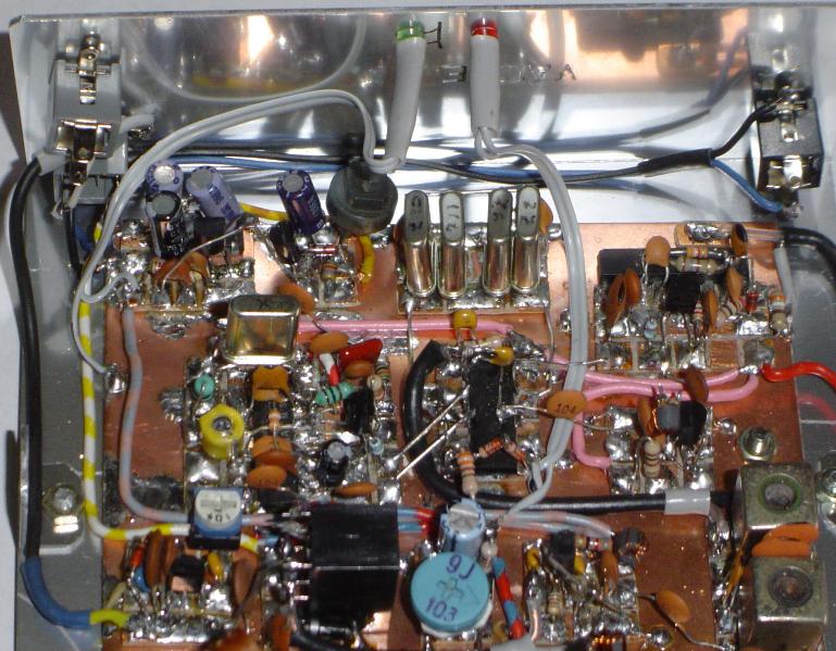
The greater inconvenient of this PLL there is no offset, it shows the controlled frequency in kHz. Another problem is the 1kHz step size that it does not allow a fine adjustment in CW or digital modes.
The easiness of assembly, the low cost and the performance are excellent.
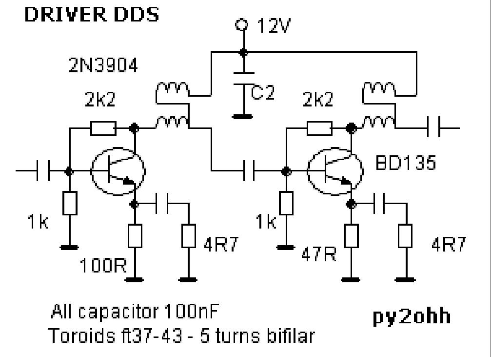
Picture: Oscillator 11 to 11.5MHz using a ceramic resonator PLL controlled, it works fine dispite the small size. It is used with BITX15 and ARARINHA 21MHz wich has 10MHz IF. The new oscillators have connections with PLL by two banana stereo plug, it is ease to make small size holes in the case box.
73 from py2ohh miguel
دوست عزيزم اقاي محمد رضا رنجكش اين دستگاه را ساخته اند
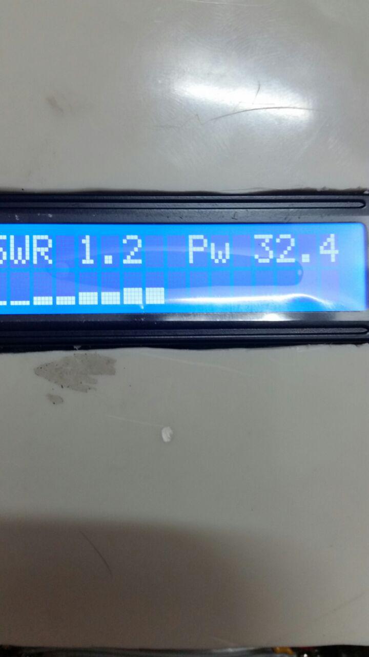
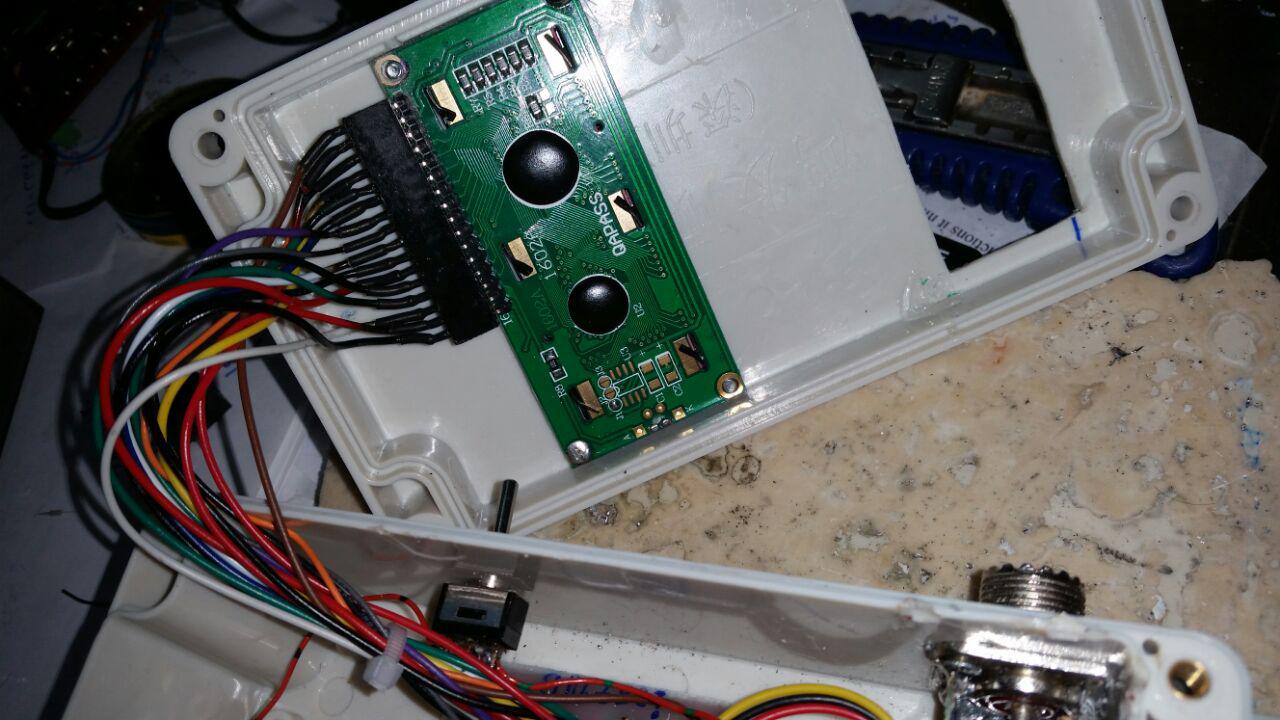
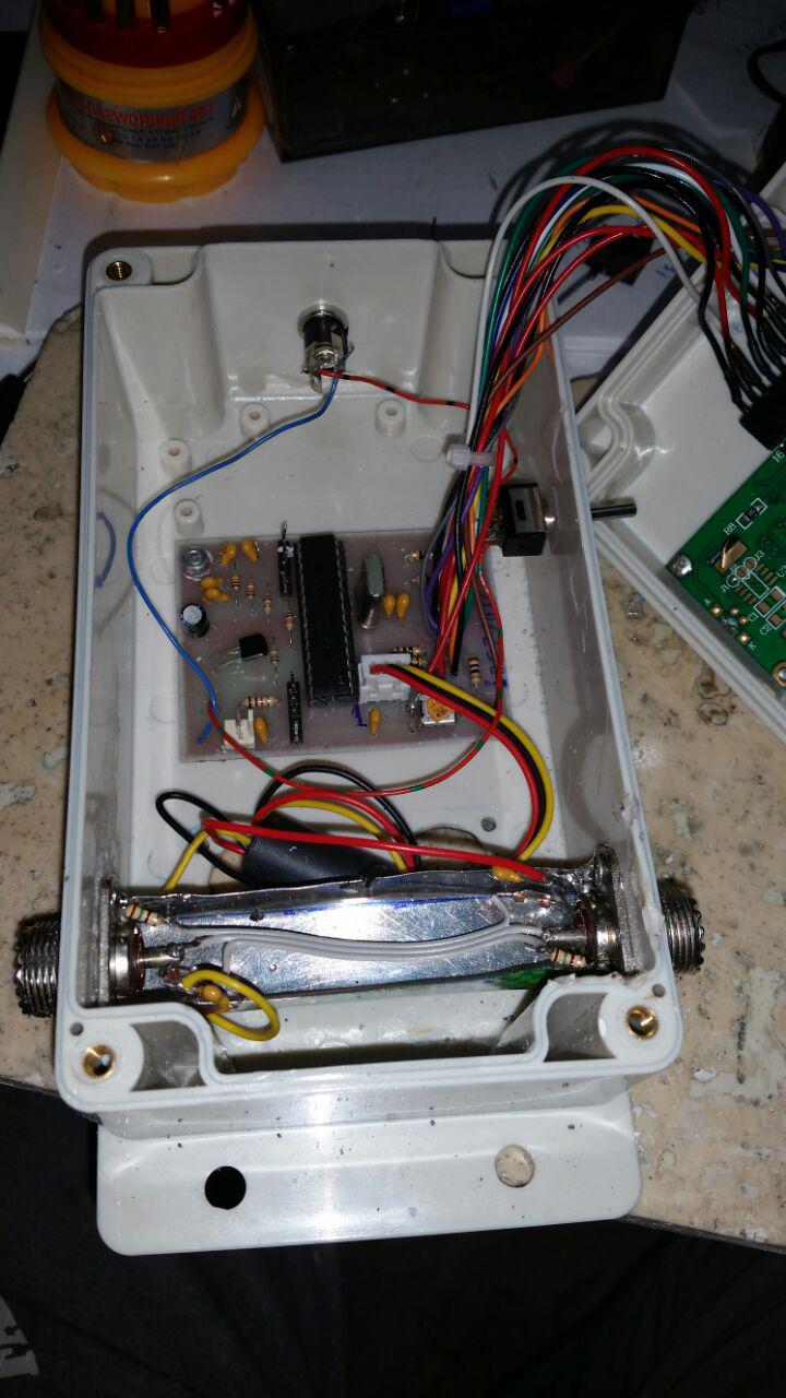
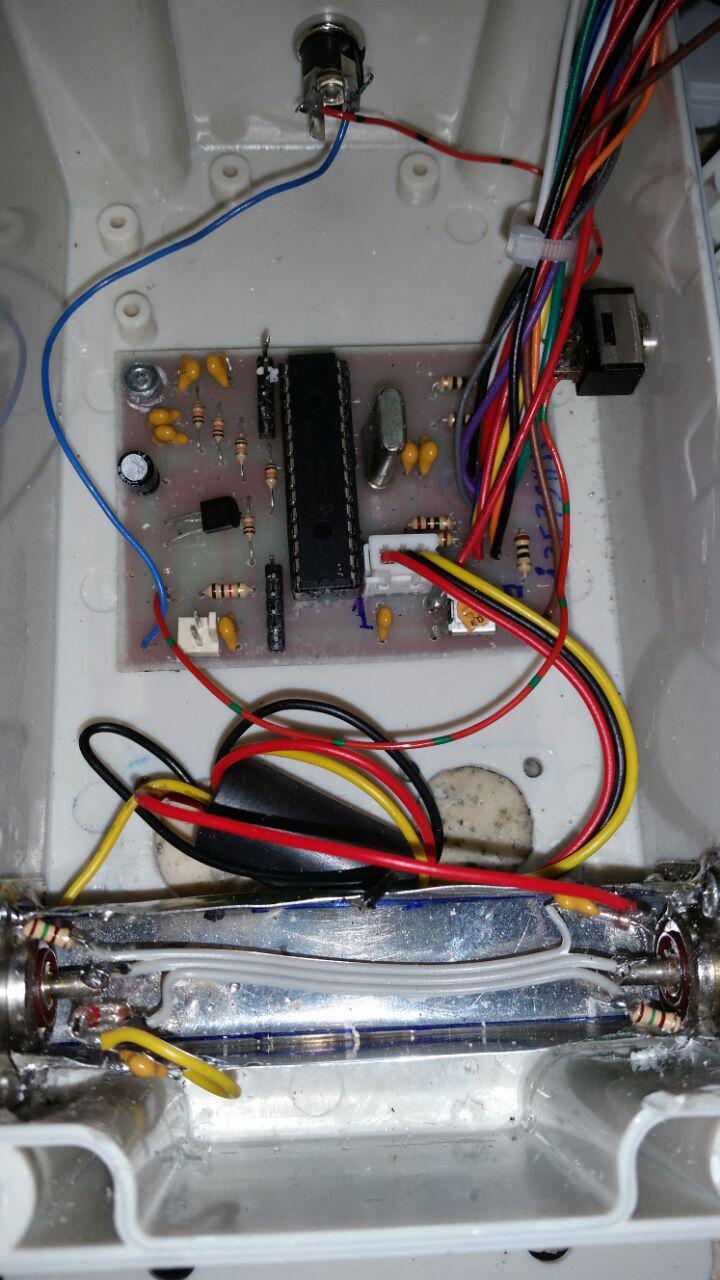
my friend Mr. Rezaee vswr meter
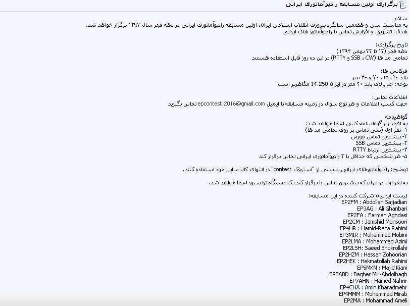
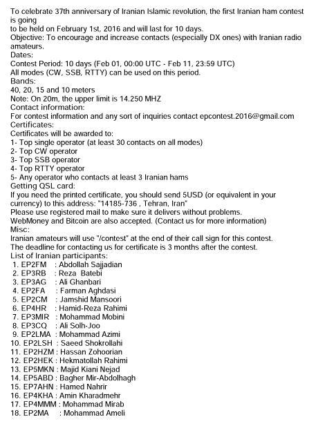
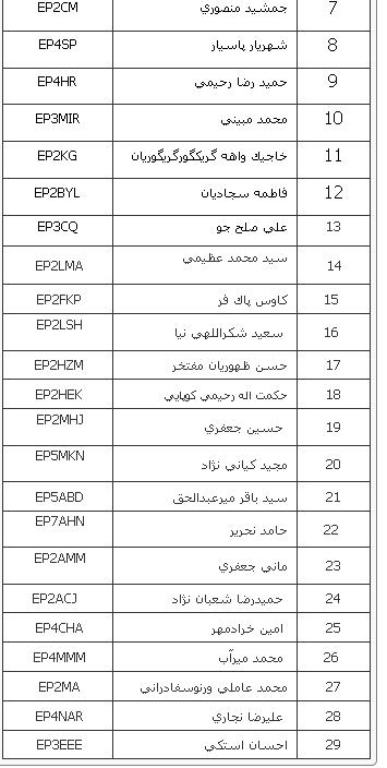
http://www.dxcoffee.com/eng/2016/iranian-contest/
ARDUINO project
AD9850 DDS based Antenna Tuner Adjustment Aid
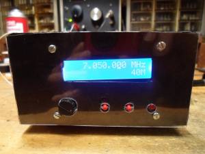
If you use a manual antenna tuner to match your transmitter to the antenna, not causing QRM while your making the adjustments can be an issue.. This project eliminates that problem by using a very low level signal and a very sensitive SWR bridge.
An inexpensive Arduino board is use to control a AD9850 DDS module and LCD display, while a handful of discrete parts comprise the SWR bridge. A simple LED is used as the match indicator.
Operation:
It is very simple.
A preprogrammed frequency for each of the HF bands, 160 to 10 meters is selected by repetitively pushing the [ CHANGE BAND ] switch. I programmed in the various QRP calling frequencies in the CW segment of each band. You can of course change that in the Sketch by changing the frequency (freq) in the band look up table.
The operating frequency can be changed using a rotary encode with Gray code output. If the frequency changes in X2 steps, you have an encoder with quadature output.
The default tuning rate is 10 kHz, which allows for quickly moving the frequency to another part of the band. The tuning rate can be changed by pushing the [ CHANGE RATE] button. 10 Hz, 100 Hz, 1 kHz and 10 kHz rates can be selected. The active decade for tuning is indicated by the cursor underscore of the selected decade.
Note that tuning limits are enabled so you can't tune outside of the selected Ham band.
Once the desired band and frequency is selected, the [ TRANSMIT ] toggle switch is used to turn the DDS signal on and off. .
When the [ TRANSMIT ] switch is closed, the DDS is loaded with the frequency data, a 600 Hz sidetone is generated and Pin 8 is set HIGH, which can be used to control a power amplifier or switch over relay. When the [ TRANSMIT ] switch is open, it loads 0 Hz into the DDS chip, effectively turning it off. You don't want to leave it on or there will be a birdie at that frequency in your receiver.
You will of course need a coax switch ( or relay) to switch the antenna tuner between this device and your rig.
With the tuning aid connected to your tuner, adjust the tuner to make the indicator LED go out or to dim as much as possible.
Theory of operation:
The SWR bridge and indicator:
The SWR bridge is a Whetstone configuration, with the antenna in the unknown leg of the bridge. If the resistance of each leg is equal, there is no voltage difference between the center of the two legs, which indicates a match. I used 51 ohm resistors in the bridge as their close enough to 50 ohms, but if you do want an exact 50 ohm match, use 100 ohm resistors in parallel instead.
The bridge is driven by the square wave output of the AD9850, through a simple L/C low pass filter to remove most of the harmonics. With out this filter, harmonic from the square wave drive will reflect back and keep the LED from going completely out or at least get very dim. The filter starts to roll off at about 2 MHz so there is still enough harmonic energy when operating below 30 meters and the best you can do is make the LED very dim. You can still achive a 1:1 match without using the low pass filter, but the dip is much harder to see.
If the resistance of the unknown leg is not equal to the value of the other three resistors in the bridge, there is a voltage difference between the centers of each leg. This voltage is coupled to a high gain darlington amplifier using a step up transformer. R1 and R2 supply just enough voltage bias to the base of Q1 to improve the sensitivity without actually turning it on. A LED in series with Q2 which provides a visual indication of the amount of current flowing into the amplifier. The greater the imbalance of the bridge, the greater the voltage inputted to the amplifier and the greater the current in the collector path. The is only one potential problem with this method. If you live near a AM broadcast station you might pick up enough signal to keep the LED on all the time as you won't be able to balance the bridge at that frequency.
Construction:
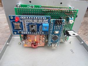
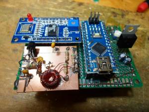
I intially used a UNO R3 board for develpoment, but used a NANO board for the final assembly. The schematic show wiring for the NANO board. Because the AD9850 and the LED back lighting of the display use a fair amount of current, a seperate 5V regulator is used to power these devices, rather then using the 5V regulator on the NANO board, as it would likely get very hot.
There are two types of AD9850 DDS modules available from China. I used the one with the two rows of 20 header pins and looks like a large DIP IC. If you use the other flavor, just follow the hook up diagram to connect to the required pins. These DDS modules are running about $10 at the time of this writing. Pretty amazing since the AD9850 chip costs $21 if you bought it all by it's self.
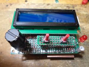
The LCD is a common 2 line, 16 character display. The ones with blue back lighting are very common and inexpensive. These run about $3.
All three of these major components can be obtained inexpensively direct for China buying with ebay. It just takes a few weeks to get them. If your in more of a rush, banggood.com can ship these from a US warehouse for a small price premium.
The rest of the discrete parts needed to build the SWR bridge and indicator can be obtained for the usual sources like Mouser or Jamesco. The MSP5179 transistors have a 1 GHz hft, so they still have decent gain at 28 MHz. You could sub the more common 2N3904's but it won't be as sensitive on the higher bands or may not work at all. If the LED does not light or is very dim at the higher frequencies, you don't have enough gain.
Since most of the componets are modules, I buit the project on a piece of FR4 pref board, using SIP sockets for the modules to plug into. The SIP sockets come in 40 pin strips. To cut them down to size, remove the pin one location past the number of pins you need and cut that slot with an hobby knife of razor saw. I use #28 heat stripable magnet wire to make all the interconnections. That way I don't need to strip insulated wire and makes for a neat looking wiring job.
The SWR bridge and amplifier could have been wired up right on the perf board, but I built it on a small scrap of copper clad board, dead bug style, which is a bit quicker and easier way to build it.
For final packaging, I recycled an old Radio Shack enclosure. Since the front panel of this box already had a number of holes in it (all in the wrong places, except for the display window, which was cut for a smaller display) I had to cover the old holes up somehow. I did this by simply putting down some double sided tape on the panel and then laid down a piece of black contruction paper and trimmed it to fit. This is then covered with a thin piece of clear Polycarbonate, which is easy to work with.
Programming the Arduino and the program "Sketch":
Hopefully your already familiar with the Arduino. If not a simple web search will come up with linksto the official Arduino web site with all the info you need.
The Sketch which you need is located in this zip file: Arduino_9850_sketch.zip
Once the Sketch has been downloaded into the Arduino board and everything is wired up, you will have to make one adjustment on the DDS module board. With the "unknown" leg of the bridge open, adjust the little trimmer resistor on the 9850 module until the SWR indicator LED comes on brightly. This trimmer sets the duty cycle of the square wave output and you want it more or less centered at 50%, but without a 'Scope just set it in about the middle of the adjustment range which makes the SWR LED stay on.
Parting thoughts:
This is my first Arduino "Sketch" and I'm pretty amazed I was able get it to work. I did take some late nights just to figure out how to do some simple things. I normally program directly in assembly which makes a whole lot more sense to me and is vasty more memory efficient and faster.
Although I designed this for the SWR bridge application, it can also be used as a signal generator, a transmitter VFO or even the VFO for a transceiver, although some modifications to the Sketch will be required for other applications.
For use as a signal generator with full tuning range, comment out the band limit tests in the DDSincerment() and DDSdecerment() routines and enable the max freq and min freq limits instead.
For a transceiver, you can add or subtract an offset to the base frequency before loading the DDS chip.
Anyway, I hope someone finds this project useful.
73, Steve KD1JV




مطلب فوق را جناب مهندس رسولي ارائه كردندو ازين بابت بسيار سپاسگذارم
با سلام
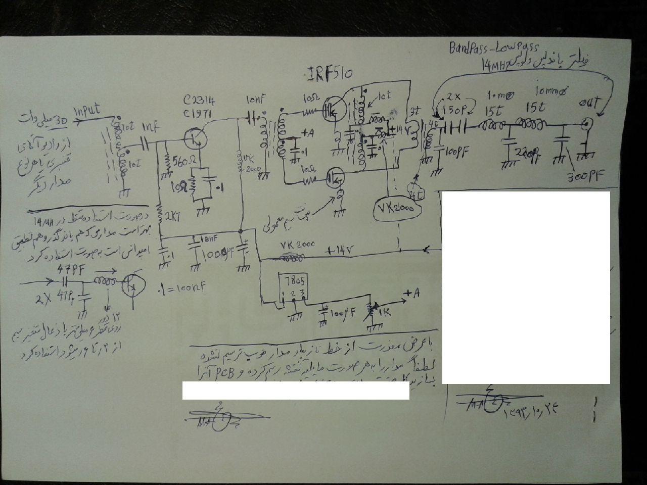
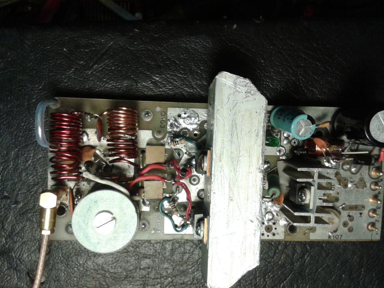
دوست عزيزم مهندس دل قوي توانستند با ترانزيستور هاي سويچ خانواده IRF تقويت باند پهن اچ اف بسازند
طرح اوليه متعلق به مهندس عاملي است كه با تغييراتي توسط مهندس دل قوي فعال شده و خروجي راديو گيرنده مولتي اس اس بي را 30-40 وات تقويت مي نمايد

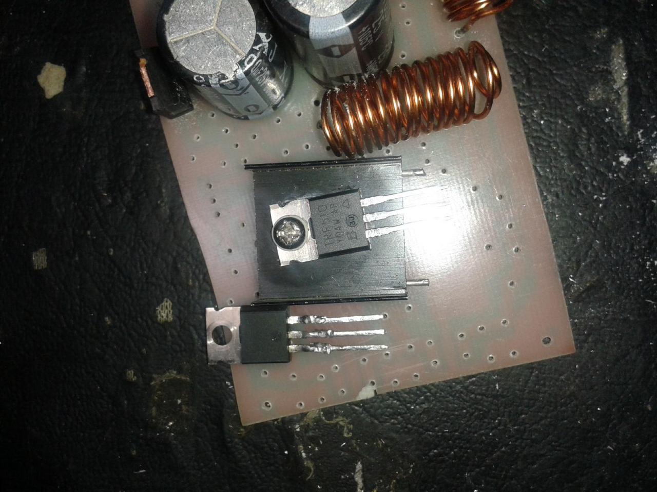
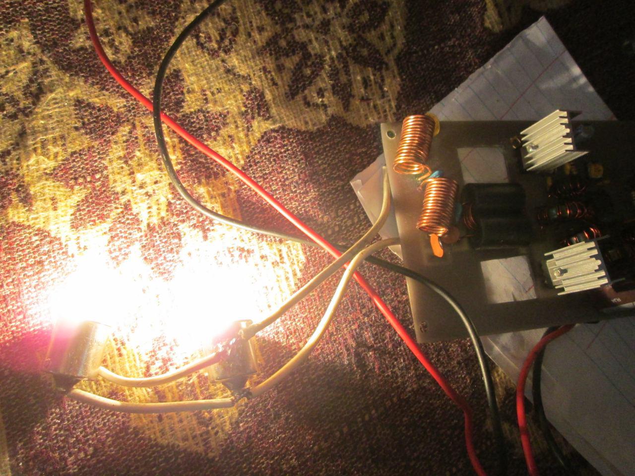
اصل طرح و نمونه برد مهندس عاملي
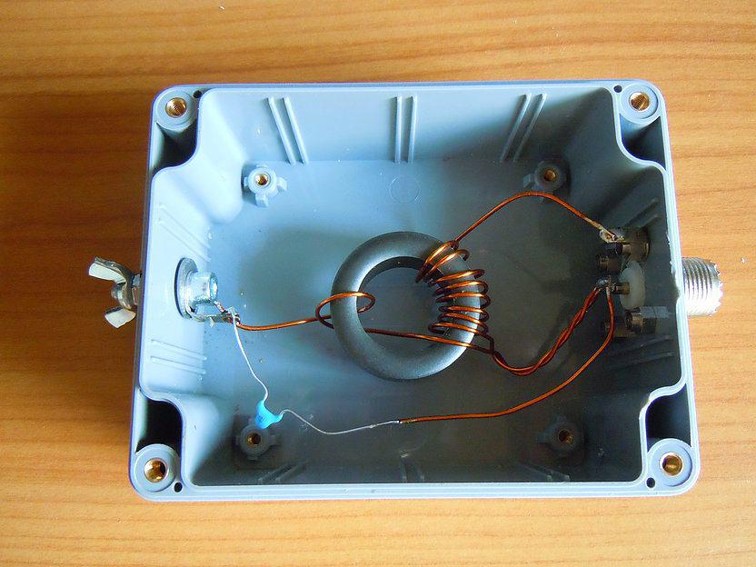
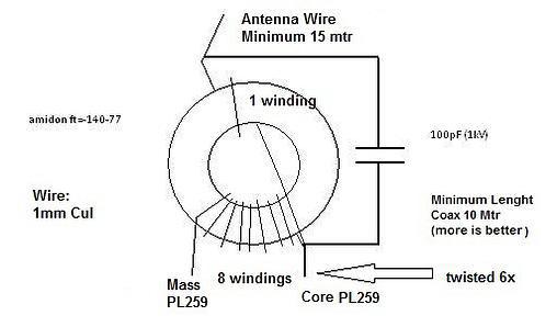
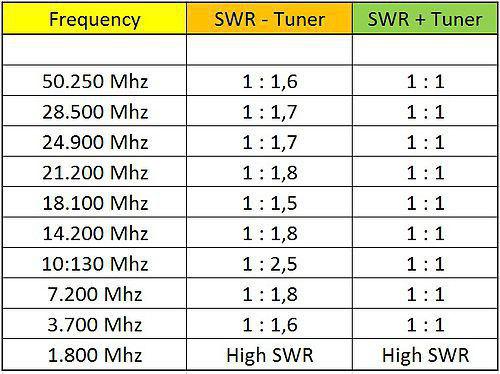
با سلام مدار جالبي براي تمام باند اچ اف با 15 متر سيم
طرح توسط مهندس حميد مثيمي اراعه شده است
ادرس اصل طرح و توضيحاتش:
http://gerritvinke.wix.com/hamradio-pa3dwc#!broadband-antenna/c158s
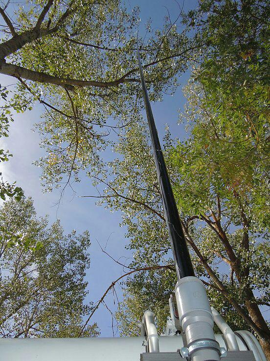
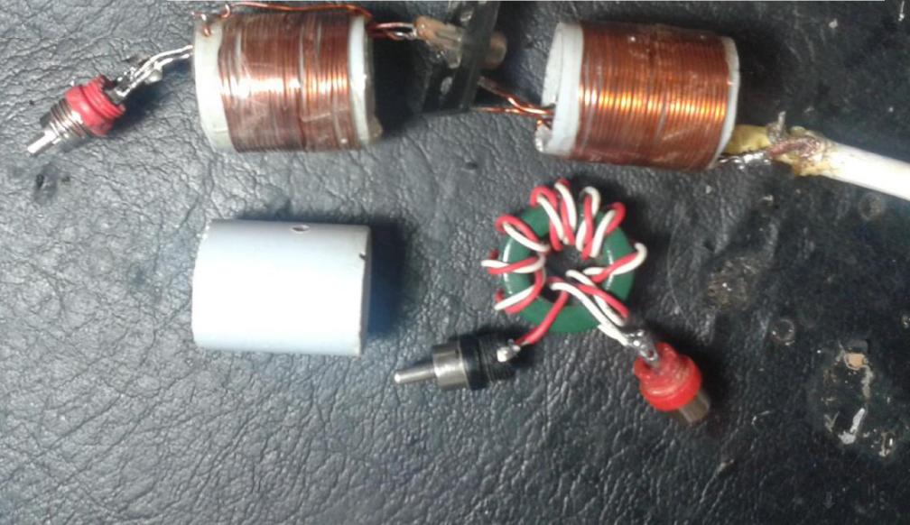
با سلام مطلب جالبي راجع به كاربرد بالون در انتن اچ اف

با سلام
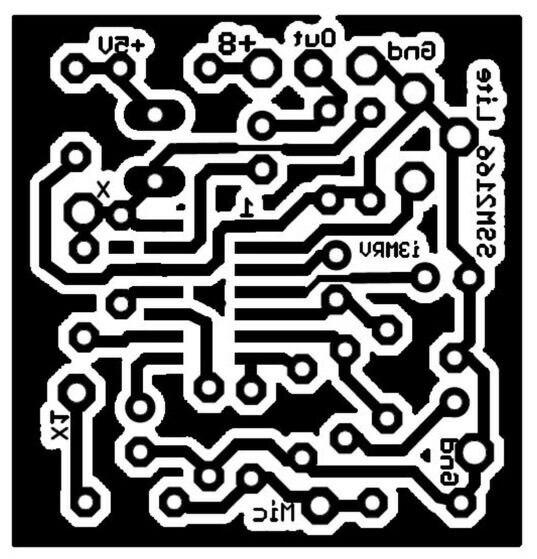
چند نفر از دوستان مدار كنترل سطح خودكار صداي ميكروفون براي مدولاسيون SSB ساخته اند كه بسيار خوب عمل كرده و صدارا كمپرس نموده و در ارسال سايد باند ثبات بسيار جالبي ايجااد مي كند
مدار اول متعلق به مهندس كياني EP5MKN مي باشد
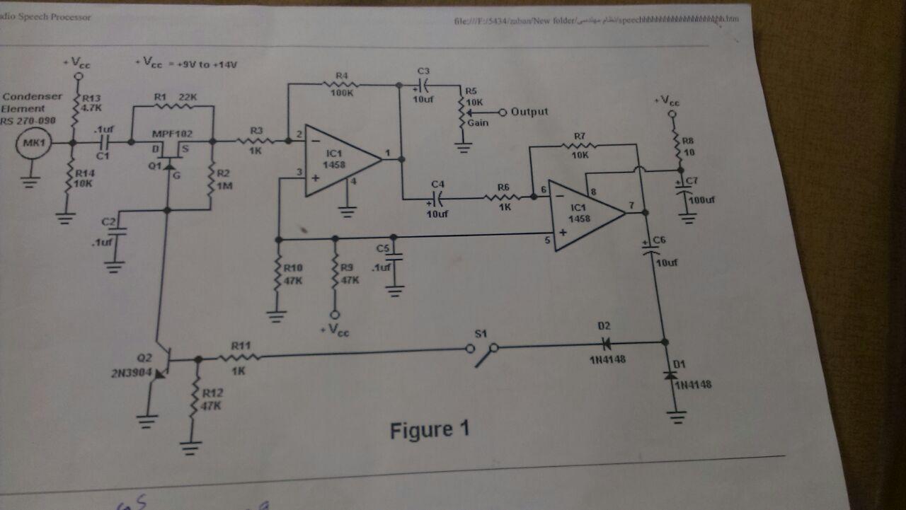
مدار بعدي ساخته مهندس ظهوريان است
EP2HZM

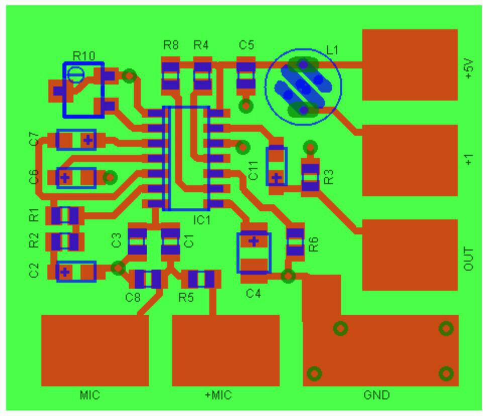
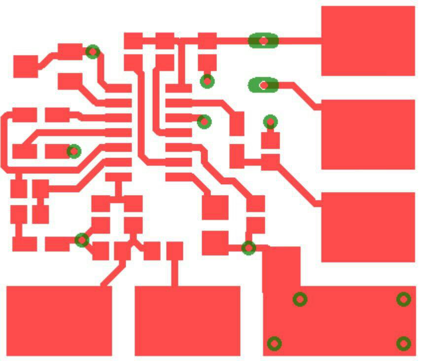
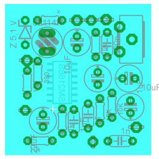
با سلام در ادامه مطلب مهندس سهرابي مدار تقويت كننده ايشون تقديم مي شود
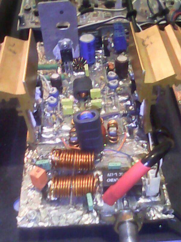
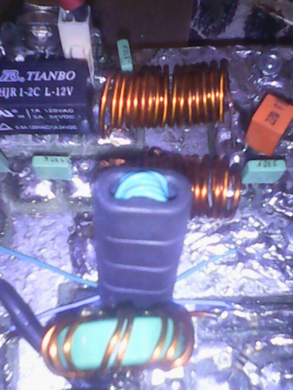

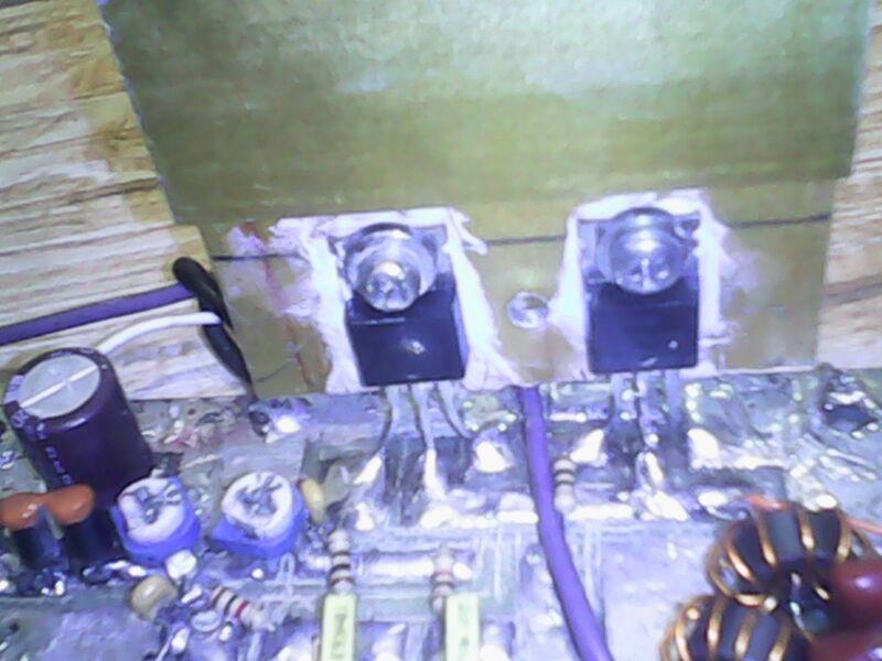
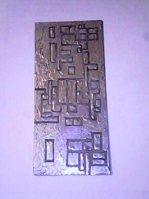
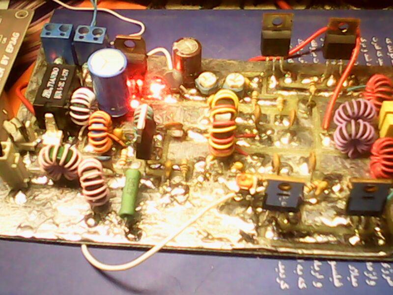
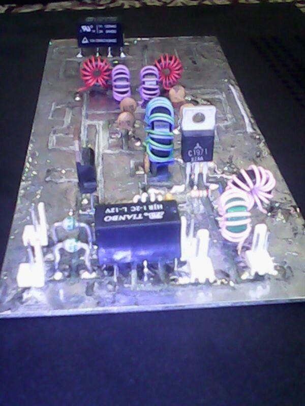
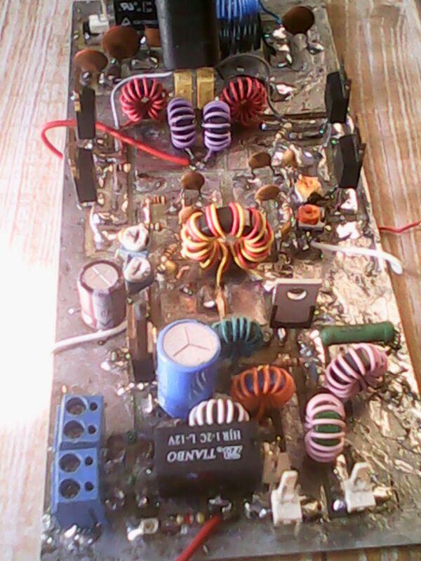

با سلام
يكي از دوستان و علاقمندان مدارات الكترونيك و از مشتريان پروپاقرص مهندس عاملي جناب مهندس محمد سهرابي چند طرح ايشون رو ساخته و تكميل كرده اند
1- فرستنده گيرنده 27 مگا با توان ده وات و سوپر هتروداين كريستالي


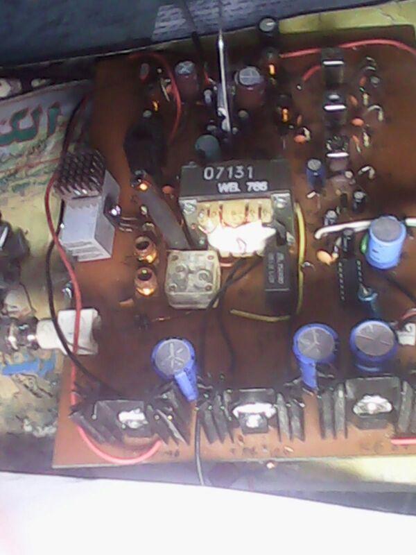

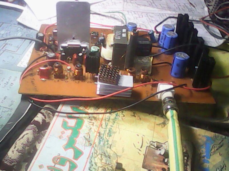

با سلام
جناب مهندس رئیس دانا بنیانگذار مجلات و نشریات علم الکترونیک و مخابرات و رادیو تلویزیون ایران وبلاگی دارند که توسط ایشان مطالب بسیار وزین و با ارزشی منتشر می گردد
سعی من استفاده از مطالب گهربار و جالب ایشان است و دوستان و علاقمندان را نیز توصیه به بررسی ان می نمایم
با آرزوی توفیق روز افزون و موفقیت بیش از پیش ایشان
etesalkootah.blog.ir
با سلام تازه ترين طرح مدار تطبيق امپدانس انتن از مهندس قنبري
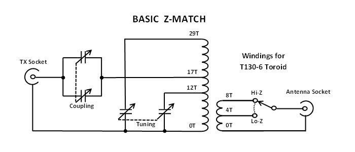
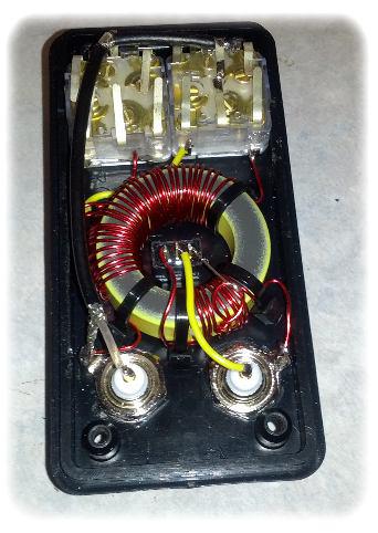
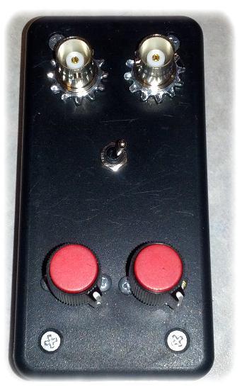
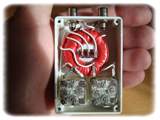
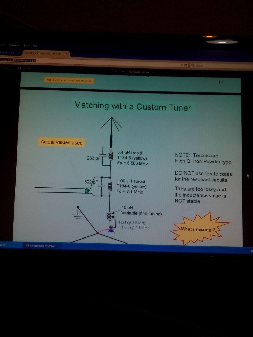
با سلام
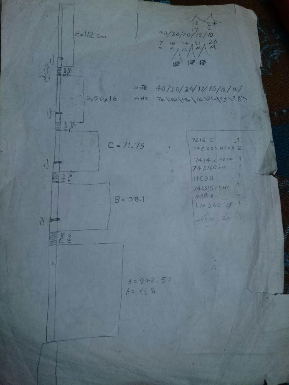
يكي از دوستان راديو آماتور جناب مهندس حسن ظهوريان EP3HZM انتن دايپل چند باند ساخته اند كه منبع بررسي و تحقيقات و ساخت انراهم ذكر نموده اند
ضمن تشكر و نمايش انتن طراحي ايشان توضيحات نيز ضميمه مي شود
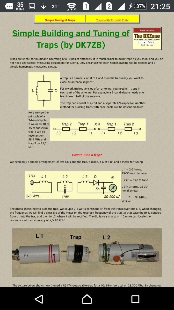
نحوه تنظيم و ساخت مدار تست تراپ ها
روش ديگر ساخت تراپ با استفاده از فيبر مدار چاپي دورو بجاي خازن

مدار تست تراپ


با سلام و تبريك ايام
دوستان و علاقمندان به راديو آماتوري
لطفا نسبت به ارسال درخواست شركت در ازمون راديو اماتوري اقدام فرمائيد
در سايت هاي زير فرم ثبت نام اورده شده و در صورت رسيدن به حد نصاب ازمون برگزار خواهد شد
لطفا به اطلاع دوستان خود هم برسانيد تا فرصت باقي است نسبت به ارسال درخواست شركت در ازمون راديو اماتوري اقدام فرمايند
www.ephamshop.com
www.ephamradio.com
http://www.phonestack.com/farhan/bitx.html
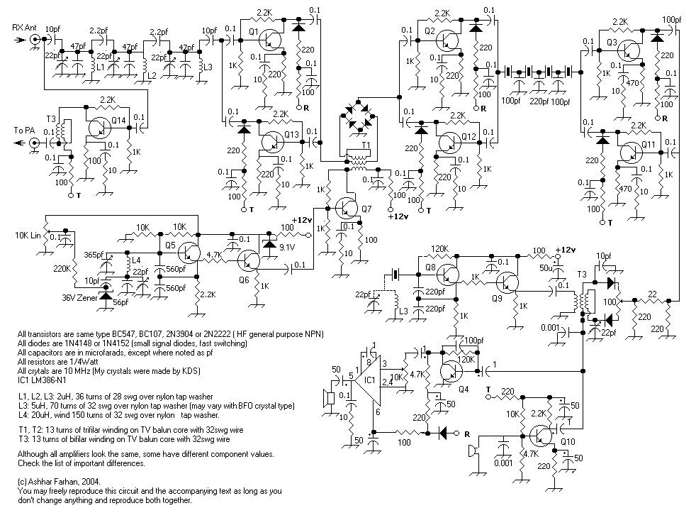

با سلام و تسليت ايام
استفاده از اردينو براي راديو

ليست صفحات
تعداد صفحات :
43

 آمار
وب سایت:


.gif)


