
تبلیغات

موضوعات

جستجو

پیوندهای روزانه

لینک دوستان
- دریافت رایگان این قالب
- سایت عاشقانه ماندگار فان
- سایت عاشقانه عشق آفرین
- جامعه رادیو اماتوری ایران
- سازمان تنظيم مقررات و ارتباطات راديوئي
- شرکت اروم الکترونیک
- فروشگاه قطعات الكترونيكي
- ARRL • Devoted Entirely to Amateur Radio
- درددل های یک بازنشسته
- نخستین سایت آموزشی رادیو آماتوری در ایران
- نشریات آماتوری
- EP2MRD
- QRZCQ - The database for radio hams
- شناسه تخصيص نحوه دستورالعمل ايستگاه به ارتباط راديويي هاي ) Call Sign ( دستورالعمل ارتباط شناسه تخصيص نحوه ايستگاه به راديويي
- رادیو آماتوری
- کلوپ رادیو آماتوری ایرانیان
- ارسال لینک

صفحات جانبی

امکانات جانبی
 آمار
وب سایت:
بازدید دیروز : 1060
بازدید هفته : 1231
بازدید ماه : 25954
بازدید کل : 2357035
تعداد مطالب : 673
تعداد نظرات : 121
تعداد آنلاین : 1
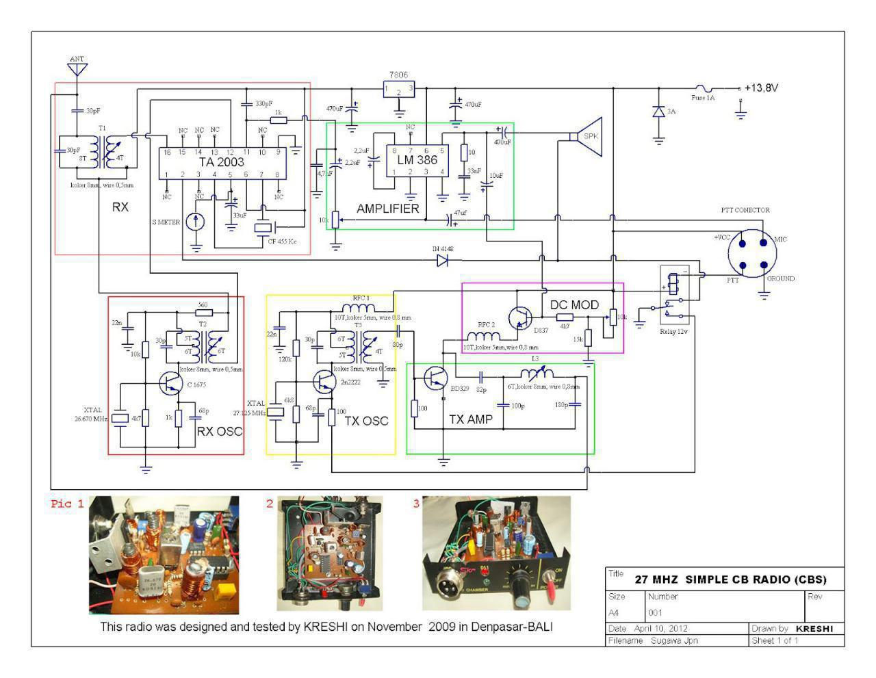
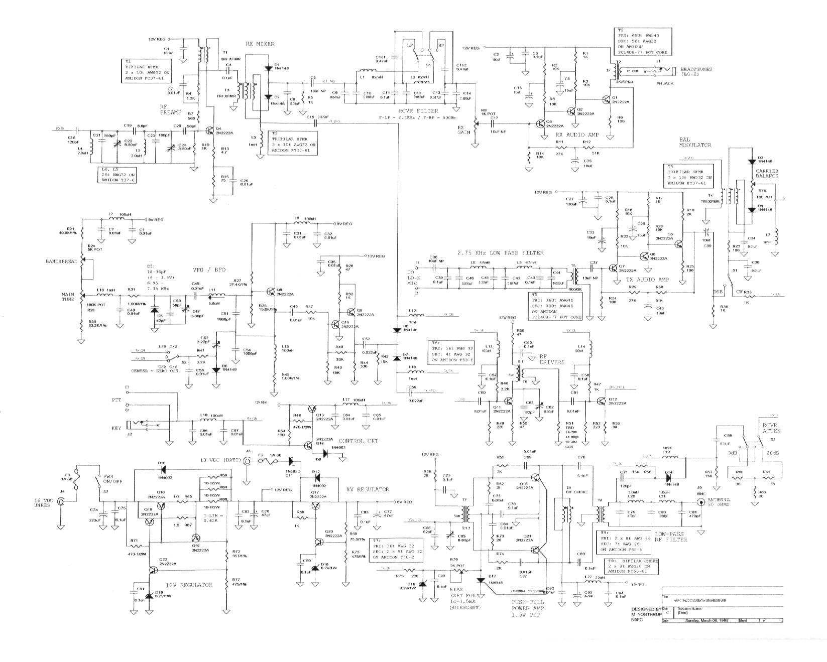
27 mhz simple radio
سلام روزتان بشادی
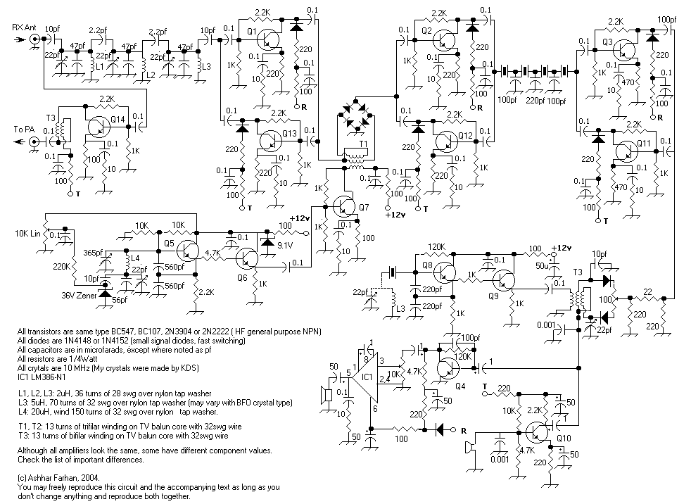
طرحی از رادیوی 27 مگا توسط مهندس علیرضا سیفی ترجمه و در گروه رادیو اماتوری اراعه گردید که بدلیل سادگی تقدیم دوستان می گردد در صورت علاقه سوال یا توضیح یا راهنمایی اگر لازم بود اماده پاسخ گویی توسط اعضای محترم گروه و استادان 27 مگا یا بقول دوستان فرکانس مهندس عاملی هستم


QRP 8W @ 13.8V 1.35A
QRP 8W @ 13.8V 1.35A
40m band
This is the end of ARARINHA project, I will add CW and further others bands.
ARARINHA is simple to build and to adjust, I will describe the circuit and add details and tips of building.
This schematics is the ARARINHA 4 normal.
مقايسه دو روش نوسانسازي ماكرويو
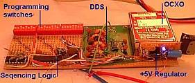
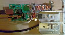
Written by Hans Summers
Wednesday, 06 April 2011 11:03
The Si570 is a relatively new device made by Silicon Labs. It's a very small device containing a crystal reference oscillator, digital Phase Locked Loop (PLL), and I2C interface so it can be programmed for any frequency between 10MHz and 945MHz (selected frequencies to 1.4GHz). Direct Digital Synthesis (DDS) chips such as those from the market leader Analog Devices have been around for longer. They are very different kinds of parts, even though they are both oscillators. Accordingly the best choice depends heavily on the application. These are my opinions about the relative advantages and disadvantages which may be important factors for your decision.
Projects
Experimental DDS project Si570-based QRSS transmitter
Reference data
Analog Devices DDS page
Analog Devices AD9910 DDS datasheet
Analog Devices AD9912 DDS datasheet
Silicon Labs
Si570 datasheet
Ease of Construction
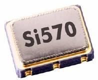
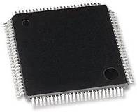
Package comparison (not to comparable scale):
AD9910 DDS (QFP100) Si570 (7 x 5mm package)
The Si570 wins here. It has 8 pins, and although a small surface mount package, you can still solder it reasonably easily, even with no PCB. On the other hand, all of the modern DDS devices are in surface mount packages only, for example this 100-pin AD9910 DDS. Soldering that one ugly-style would be a challenge. Even the earlier generation DDS's with 28 pin SMD's weren't easy.
Output waveform
The Si570 has a squarewave output. Often that's fine, for example, if you want to drive a mixer with it: many mixers operate best when the VFO is a squarewave. If you want a sinewave, you'll need a lot of low pass filtering to get rid of the rich suite of harmonics.
DDS chips have a sinewave output: it is generated by the rapid output of a succession of analogue voltages via a Digital-to-Analogue converter (DAC), which approximates a sinewave. Many of the DDS chips have an onboard comparator which can easily be used to turn the sinewave output into a squarewave, if that's what you need. Bear in mind though that you need an anti-alias low pass filter on the output of DDS chips to produce a clean output.
Which one wins... depends on your application. If you only need a squarewave, Si570 is fine. DDS can do either (if it is one of the ones which has a comparator on board), so for that reason, my winner is DDS.
Frequency range
A DDS will function right down to near DC. The practical upper range of a DDS is normally considered limited to 40% of its reference clock oscillator. This is a limitation of the digital synthesis of the waveform, which is a sampled process (look up Nyquist). Frequencies higher than 40% of the reference clock oscillator are also possible at the output of the DAC which is unfiltered, and these could be extracted by suitable bandpass filtering instead of the usual low-pass filter. Outputs like this require more detailed design and the performance is unlikely to be as good.
By contrast the Si570 allows any output frequency from 10MHz to 945MHz, and a more limited selection of frequencies all the way up to 1.4GHz. I have heard that operation below the specified 10MHz lower limit is possible too but have not confirmed this myself.
Here I'd say the DDS would win if you wanted to be able to go down to very low frequencies, but the Si570 would win if your application needs very high frequencies, or a very wide continuous range up to UHF and beyond. But because the Si570 has such a large and convenient range, let's call it the winner.
Frequency stability/accuracy
DDS requires a reference clock oscillator, which one normally provides with a high stability crystal oscillator. You have to provide the crystal reference oscillator. You can make it as accurate and stable as you like. GPS-lock it, lock it to a Rubidium standard, put it in a constant-temperature oven... whatever you like.
The Si570 has its own crystal oscillator built in. The difference here is that you have not much control over the internal oscillator of the Si570. You can't adjust it to be exactly on frequency, you can't lock it to a frequency standard or GPS reference. (It does have some frequency adjustment via an ADC input, but you'd still need to measure the actual frequency, compare it to a standard, and estimate a correction voltage - so it doesn't really do the job except with extreme effort). In my Si570-controlled QRSS beacon I found that the Si570 was already quite accurate and stable: A few Hz off frequency at 10.140MHz and it did not seem to drift perceptibly with room temperature variations, though neither of these measurements were detailed.
In my opinion, if you need stability and accuracy, DDS wins here, because you can make it as accurate and stable as you like.
Frequency agility
The frequency of a DDS can be set almost instantly (at least, as fast as you can clock your new desired frequency into the chip)! Most DDS chips have at least 32-bit tuning word resolution, and some of them even have 48-bit tuning word (e.g. AD9912) giving you tuning resolution down to steps of a few micro-Hz, if you should ever need it!
Si570's can also be tuned in very small steps but the frequency does not change instantly. When you make a change in frequency, there is a delay of up to 10ms (0.01s) while the internal PLL locks on to the new frequency. That can sound like a small click/chirp in your receiver audio for example, if you are using the Si570 as your receiver VFO. The Si570 can also be tuned much faster (100 times faster) for small steps within 3,500 parts per million (ppm) of the centre frequency. In this case, the settling time is less than 0.1ms (100us).
This delayed tuning of the Si570 might make it unsuitable for some applications, e.g. digital communications modes where the frequency must be changed quickly, or split frequency operation, or perhaps QSK CW with an offset between receive and transmit (though this would be unlikely to exceed the 3,500 ppm needed for a large-step).
So for frequency agility, the DDS definitely wins if your application needs it: frequency changes are as good as instant!
Programming interface
The DDS chips have a serial programming interface, and programming is easy. Some also support a parallel programming interface (one byte at a time). I built a DDS generator which can be done without a micro-controller at all (see here) but normally you'd be using a microcontroller.
The Si570 has an I2C interface, and programming the frequency you want is a little more tricky - involving some calculation of different multiplier/divider values and the internal digitally-controlled-oscillator frequency. A little more complex than the DDS programming word, which is a simple fraction of the reference clock frequency.
The Si570 is still not a problem if you're reasonably competent with programming microcontrollers, but as the DDS is more straightforward it has the lead here, I think.
Performance: Spurs
The Si570 is a digital phase locked loop oscillator producing a squarewave output. As all squarewaves, this is a fundamental plus a rich comb of odd harmonics. If a sinewave is required and the range of operation is narrow, the spurs can be filtered out if required, and are of course a reasonable distance from the carrier (i.e. at 3, 5, 7... times the fundamental carrier frequency). There is some harmonic content on even harmonics too as the output is not guaranteed to be a perfect 50% square wave. Other spurious responses are very low for the Si570 and not normally considered to be a problem.
DDS chips have a bad reputation for spurs! This is because the output sine waveform is approximated by a series of discrete steps, which are later filtered external to the chip by your low pass filter. The process is inherently a discrete appoximation of the ideal sinewave, which generates spurious responses. The spurii are numerous and at various different amplitudes, and also can occur very close to the carrier, so you cannot filter them all away.
Some of the most modern Analog DDS chips include a "SpurKiller" technology, such as the AD9912 with two SpurKiller channels. These are effectively two parallel DDS cores, whose frequency and output amplitude and phase can be set up such that if your application can predict or measure the location of your spurs, you could choose your two most objectionable spurs, and eliminate them by cancelling them out. I think the range of instances that this would be useful would be somewhat limited. The datasheet mentions that this feature performs optimally slightly differently on each device, which would further limit its usefulness in many practical applications.
The seriousness of the spurs problem depends mainly on two factors: the resolution of the DAC and the proportion of the output frequency relative to the reference oscillator frequency. DAC's typically go from 10-bits in some earlier devices up to 14-bits in a top-of-the-range device like the AD9912. A higher resolution DAC produces less spurs. Similarly if the reference oscillator frequency is very high relative to the output frequency, spurs are reduced. The AD9912 can operate with up to a 1GHz reference oscillator. For output frequencies in the 0-30MHz HF range, the spurs are very minimal. For VHF or UHF output frequencies the spurs could be more objectionable for sure. For amateur radio use, even on a low-end DDS, spurs are unlikely to be a problem in purely transmit applications, because they are less than the legal spurious output limits of amateur radio equipment. In receive applications, spurs will show up as birdies in the receiver, and are more serious. However, for an HF receiver if you were using a modern DDS such as the AD9912 with 1GHz reference clock oscillator, then the spurious content would be very low and unlikely to be noticeable in most cases.
A high-end DDS with careful design hasn't got spurious response problems under a limited range of circumstances i.e. at HF. But the Si570 wins on this one because it doesn't have spurs problems anyway.
Performance: Phase noise
Phase noise can be imagined as a widening of the theoretical perfect vertical line you would see on a spectrum analyser examining the output signal. One reason why it is important in a receiver, is that it mixes with strong signals some kHz away from your wanted signal to produce an elevated noise floor, which could easily obscure a weak signal you want to listen to. For a high performance receiver, it is really important to use a low phase noise local oscillator.
The phase noise performance of DDS is generally very good. There is a little jitter added by the imperfections inherent in the digital waveform approximation and some general very limited phase noise added by the imperfections of this digital device. Also the DDS phase noise can only ever be as good (actually slightly worse) than the reference clock oscillator. Typically this would be a crystal-based crystal oscillator, and crystals, being very high Q devices, have very good phase noise performance. So generally, DDS is considered a low phase-noise technology.
Many of the DDS chips include a reference clock multiplier PLL. This can be used to provide an internal very high frequency reference clock, up to the rating of the device e.g. 1GHz for the AD9910, from a much lower input clock oscillator frequency. Remember that high reference clocks are best, for best spur performance, so the multiplier can be useful in that regard. It can simplify your design greatly, but it comes at the price of adding unwanted phase noise in the internal PLL multiplication process. Frequency multiplication in any event carries a theoretical minimum 6dB/octave (or 20dB/decade) phase noise penalty, but if you use the internal PLL multiplier you add even more than this. So for best phase noise performance, leave the PLL switched off and build your own external high frequency reference oscillator.
The Si570 is based on a PLL technology, which generally has a much higher phase noise. However in the Si570, they minimise the phase noise by careful design and by using a very narrow loop bandwidth. This is the reason why it has a relatively slow settling time (10ms) when you change the frequency. So the phase noise of the Si570 is pretty respectable, and will probably be adequate for many applications.
How about a comparison between DDS and Si570? The phase noise performance data in some of the DDS datasheets is somewhat limited. Often they show the "residual phase noise", which means the additional phase noise which is added to that of the reference oscillator by the DDS process itself. This is not the same as the actual phase noise you would observe on the output - for that you need to also add the phase noise of the reference oscillator - so it is not directly comparable with the phase noise of an Si570. However, some of the DDS device datasheets show an absolute phase noise chart, and an example of this is the AD9912 which shows output phase noise for various output frequencies and assuming the use of a high performance 1GHz Wenzel oscillator. The Si570 datasheet has a table of phase noise at three output frequencies (120MHz, 156.25MHz, 622.08MHz).
It is important to remember that when a frequency is divided, the phase noise also decreases by 6dB per octave (or, 20dB per decade). So in any comparison, we need to take this into account if the frequencies concerned are not the same. For this example comparison, I am choosing to compare the Si570 data at 156.25MHz with a graph in the AD9912 datasheet at 171MHz. Strictly I should adjust for this frequency difference (i.e. 156.25MHz and 171MHz) by doing some mathematics for the 6dB/octave. However they are close enough frequencies that this would make only 1dB difference or so, which in any event is only about the precision I can read off the values from the chart in the AD9912 datasheet, so I'm going to ignore it for now. This small inaccuracy would act in favour of the Si570 which is at the lower frequency in this comparison.
So, here's a table of the values for 156.25MHz from the Si570 datasheet, and the corresponding values read off the graph from the AD9912 datasheet. These results would be expected to be broadly repeatable with the two devices at other frequencies, appropriately scaled by 6dB/octave (20dB/decade). The units of phase noise are dBc/Hz.
Offset Si570 AD9912
100Hz -105 -125
1kHz -122 -138
10kHz -128 -148
100kHz -135 -157
1MHz -144 -162
10MHz -147 -163
Here are those same results, represented on a graph:
The overall conclusion here has to be that a top-end DDS with quality reference clock oscillator and good design (the AD9912 at 1GHz refclk), can outperform the Si570 by 20dBc/Hz. However, I'd say that for many applications the Si570 phase noise performance would be sufficient, and probably better than many expensive commercial "black box" amateur radio transceivers on the market.
But due to the excellent phase noise performance of DDS technology, DDS is the winner here.
Power Consumption
Neither the Si570 nor DDS are exactly innocent when it comes to power consumption. Both will be agressively trying to drain your batteries, if you are operating battery-powered equipment.
The Si570 is stated to consume 120mA at 3.3V for the LVPECL, which is 396mW. An AD9912 on the other hand, requires separate voltages at 1.8V and 3.3V for its various sections (analogue and digital). Each has different current consumption, but the datasheet also lists typical power consumptions under various configurations. The power consumption is between 637mW and 747mW. The AD9912 even has an exposed copper pad on the bottom to help get the heat out! Don't forget, this is even before you consider that the Si570 has its own internal reference clock oscillator, whereas DDS chips needs you to provide one externally, which will add even more power.
Some of the older, less powerful DDS chips do consume less power. But as I've mentioned the top of the range DDS devices a lot, particularly the AD9912, I'll say that the Si570 wins on this measure.
Cost
Neither are cheap. The Si570 is a similar price to some of the lower-end DDS chips but for a high-end DDS such as the AD9910 or the AD9912 I keep mentioning, you'll be paying considerably more than for the Si570. Also the DDS require more support circuits such as the reference clock oscillator, which is also unlikely to be cheap. On the other hand, if you're a cunning (and stingy) radio amateur, you used to be able to get free DDS samples from Analog. You never could get free Si570 samples from SiLabs. Overall I think we have to say the Si570 wins on cost, generally.
Other features
The Si570 is just a plain oscillator. If you want more features, you want a DDS! Read the datasheets, and be amazed! Control the amplitude, control the phase, add spur killing. Some DDS devices contain TWO cores and outputs, which can be set to be offset at 90-degree phases (useful for phasing direct conversion mixers for example - check out the AD9854). Automate your amplitude modulation, frequency modulation, phase modulation, automatic sweep, and other kinds of features I can't even remember or understand. You probably don't need them, they're probably just sales gimmicks, but on features you have to agree, the DDS is definitely the winner.
Overall complexity
An Si570 is pretty simple to use. Just add a 3.3V power supply, connect up your microcontroller, and you're ready to go.
Not so, the DDS! With a DDS you may need four separate well-regulated and clean power supplies, some at 1.8V and some at 3.3V. You need a reference clock oscillator. Some DDS chips have an onboard oscillator where you can just connect the crystal directly to the chip. But for best performance you'll want to design and build a 1GHz oscillator, which is no trivial matter, and get that properly coupled into the chip input. Then you need the reconstruction filter (typically low pass) at the output, and that needs to be carefully designed too. The board design needs lots of care too, with all that high frequency stuff rolling around.
Yes, using a DDS is a lot more effort than an Si570. So on complexity, the Si570 is definitely the winner.
Summary
So after all that, here's my summary of my opinion on the various criteria by which to judge these two kinds of oscillator. Bear in mind that every application is different! In some applications, some of these criteria don't matter to you at all, or the decision of what is better will be clear (and opposite to my conclusion). In others, you are faced with the usual decisions about trade-offs. Performance and complexity; features and cost; etc. But I'll generalise and operate in typically bi-polar manner and give my overall winner in every category regardless, and leave the judging of your applications to you.
Category Winner
Ease of construction
Si570
Output waveform DDS
Frequency range Si570
Frequency stability/accuracy DDS
Frequency agility DDS
Programming interface DDS
Performance: Spurs Si570
Performance: Phase noise DDS
Power Consumption Si570
Cost Si570
Other features DDS
Overall Complexity Si570
Further reading
For a great inspiring read about a wonderful ultimate-high-performance receiver project, and the reasons why Martein PA3AKE chose the AD9910 DDS for his oscillator, please visit his site. For Si570 kits see SDR Kits. There are loads of DDS kits around, just google for them. For lots of interesting info and discussion about the Si570, visit Andy G4OEP's Si570 pages; like Martein PA3AKE, Andy never does anything by halves.
My Favourite
What's best really depends on the application. But if you're still reading this, and I have to choose a general overall favourite, I just have to choose the DDS. Just like a favourite colour, or a favourite lucky number, I don't need a good reason. I just LIKE it better!
Last Updated on Monday, 03 March 2014 04:54
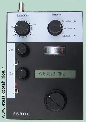
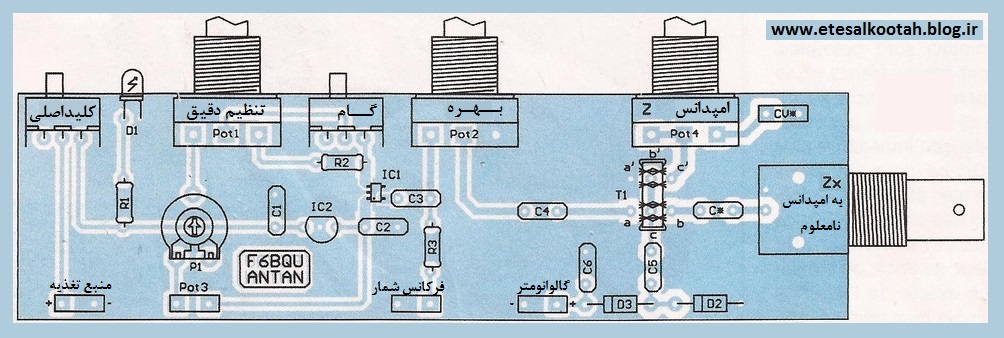
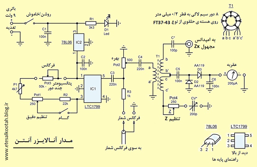
اناليزر انتن
با سلام و آرزوي موفقيت دوستان
جناب مهندس فرزاد استاد و سرور بنده در سايت وزين خود مطالب بسيار جالبي اراعه و در اختيار علاقمندان مي گذارند كه نمونه آن مدار بسيار جالب زير است

PLL SAA1057 / PIC16F84 from 500kHz to 30MHz
Picture : Our PLL, look the mouse for wired remote control.
This circuit is described in the site www.freddospage.nl, where software can be downloaded.
Although PLL SAA1057 to be discontinued, is possible finds it at low prices in the Brazilian market (R$3,50 = US$1,50).
We made the assembly in UGLY method, with small modifications.
Original project (we add 3 capacitors of 100nF):
The sigle modification was the addition of three capacitors of 100nF. This modification was necessary therefore we use a three buttons PC mouse for the place of the switches STEP, UP and DOWN, thus the control was by hand. E due to the length of the mouse cable was necessary to decoupling the RF.
The power supply comes from the Oscillator to be controlled.
Picture : We use flat cable from computer scrap, it does ease the building.

The signal of RF for frequency control, the tension of frequency control for varicaps as well as the power supply had been connected by a single DIN plug. Later we normalize our interconnections with a mini estereo banana (P2) and are necessary two, one for VCC and incoming RF signal another for referency tension for varicap.
Picture: 2nd PLL built, we use standard cupper board and the LCD is direct connected.
Picture: 2nd PLL, showing the board LCD connections.
The greater inconvenient of this PLL there is no offset, it shows the controlled frequency in kHz. Another problem is the 1kHz step size that it does not allow a fine adjustment in CW or digital modes.
The easiness of assembly, the low cost and the performance are excellent.
Picture: Oscillator 11 to 11.5MHz using a ceramic resonator PLL controlled, it works fine dispite the small size. It is used with BITX15 and ARARINHA 21MHz wich has 10MHz IF. The new oscillators have connections with PLL by two banana stereo plug, it is ease to make small size holes in the case box.
73 from py2ohh miguel
recever radio
Many thanks to David Ai2A for the excellent revision of the following text
40 m Band Superhet Receiver
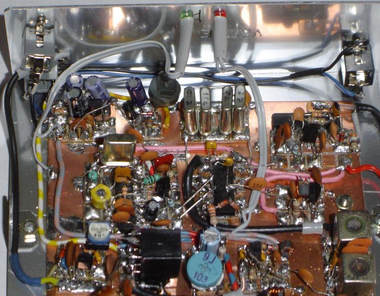
By the addition of one integrated circuit and some passive components, I was able to convert my earlier developed 40-meter direct conversion receiver design into a superhet model. Anyone who has listened to 40 meters during the evening hours on the crowded 40 m band will appreciate the advantages of the single signal reception, which this circuit offers. All simple direct conversion receiver designs suffer from degraded selectivity performance and are more subject to overload by contrasted to even modest superhet designs. Direct conversion designs are simpler by contrast because they are missing an IF stage and any associated filtering, a BFO and the second mixer.
In order to modify the design to create a superhet model, it was necessary to increase the 1st oscillator frequency from 7000 kHz - 7040 kHz to a revised range of 10686 kHz -10731 kHz (operating frequency plus the intermediate frequency). The choice of this 1st oscillator frequency turned out to be fairly easy by considering the availability of 3686 kHz crystals. Bandwidth is set to 200 Hz by a series coupled filter (using a single 3686 kHz crystal) in the IF amplifier section. This choice is highly suitable for CW operation. The choice of 3686 kHz IF allows use of readily available 10.7 mHz ceramic resonator in the 1st oscillator circuit.
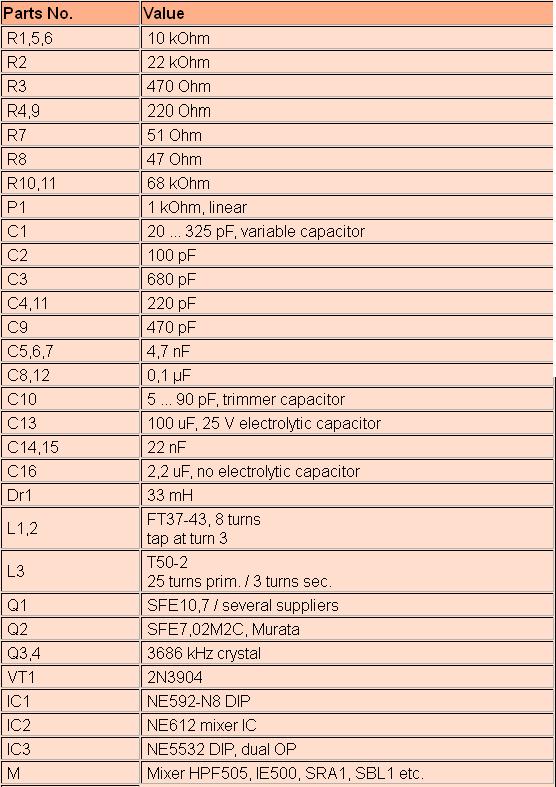
Fig.1: Receiver circuit diagram
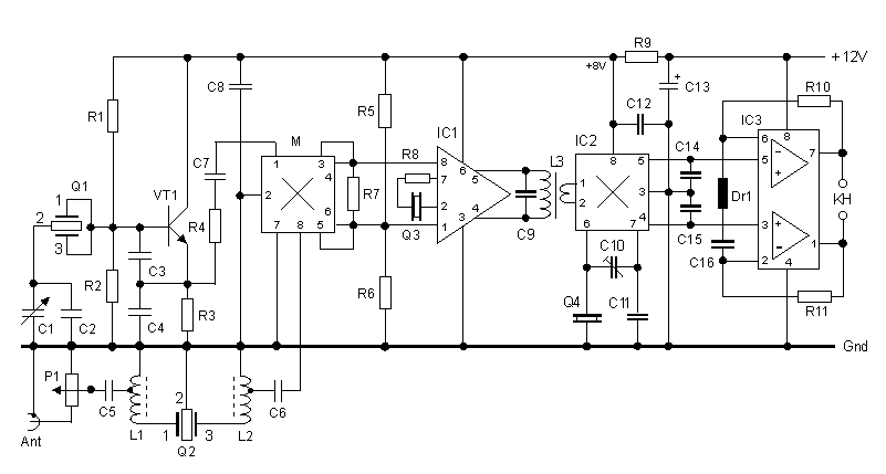
The first part of the circuit to be described is the 1st oscillator (main tuning). It is a variation of the Colpitts type oscillator. It uses a 10,7 ceramic resonator as its frequency-determining component. Unlike a quartz crystal based VXO, the ceramic resonator Q1 results in a much broader tuning range (approximately 45 kHz) while still maintaining a desired level of frequency stability at the same time.
A second ceramic resonator with a center frequency of 7020 kHz is used as a front-end filter. This effectively attenuates much of the strong S9 +40 dB strong signal interference from the 41-meter shortwave broadcast band. The shape factor and center frequency, while not a perfect choice, perform quite well. The stop band for this resonator appears to be located at 7125 kHz - well beyond the desired 7040 kHz. The availability, low price, simplicity of the circuit and absence of alignment warrant suggest inclusion of this specific device. A network formed by L1 and L2 help match the 330 ohms resonator impedance to the 50 ohms of the diode ring mixer and the antenna.
The output of the ring diode mixer is coupled to an IF stage based on the NE592 broadband amplifier. I was able to narrow the IF selectivity to 200 Hz by adding a crystal filter using series interstage coupling (formed by a 3686 MHz quartz and resistor R8) between pins 2 and 7. The mixer sees at its IF port a parallel circuit consisting out of R7 and the high input impedance of IC1. L3 and C9 form a parallel resonant circuit that is tuned to the IF. The value of C9 is not critical because the output resistance of IC1 causes strong damping.
The second mixer based on the well-known NE612 and is used as a product detector. The mixer output pins of the NE612 drive the differential input of the NE5532 audio amplifier. Any remaining RF energy present at the output pins is shunted to ground by using the two capacitors C14 and C15. These effectively couple only an AF signal output from the product detector stage into the audio amplifier.
The AF stage has a gain of 60 dB at the 750 Hz audio filter center frequency. The audio filter center frequency is determined by the component values used in the passive series resonant circuit formed by Dr1 and C16. The audio output volume adjustment is controlled with an RF attenuator control P1, located close to the antenna input. The NE5532 output resistance is relatively low, so 60 Ohms headphones can be used without an additional series resistor.
The receiver operates well across a wide range of supply voltages ranging from 9 V to 15 V. The AF amplifier is directly powered from the supply rail. The IF amplifier, second mixer and oscillator need approximately + 8 V. A series voltage-dropping resistor R9 normally meets this requirement. In practice, if the resulting voltage is less than 7 V, reduce the value of R9. Alternatively, one could use a + 8 V voltage regulator in place of R9. Without any input signal, the receiver consumes only a mere 25 mA.
Receiver alignment requires a frequency counter and an oscilloscope. First, measure the 1st oscillator frequency and observe its output voltage at pin 1 of the ring diode mixer. The frequency should be 10686 kHz with C1 at the maximum setting and 10731 kHz at its minimum setting. The measured 1st oscillator (LO) voltage applied to the mixer should measure about 0,5 Vss. If the desired frequency values are not correct, vary C3 and / or C4 slightly. Next adjust the trimmer capacitor C10. It serves to slightly adjust the BFO offset frequency and therefore the resulting received signal AF tone or pitch. The best performance will occur when the BFO frequency offset results in an audio tone of about 750 Hz (matching the passive audio filter resonance (C16 and DR1).
AD9850 DDS based Antenna Tuner Adjustment Aid
ARDUINO project
AD9850 DDS based Antenna Tuner Adjustment Aid
If you use a manual antenna tuner to match your transmitter to the antenna, not causing QRM while your making the adjustments can be an issue.. This project eliminates that problem by using a very low level signal and a very sensitive SWR bridge.
An inexpensive Arduino board is use to control a AD9850 DDS module and LCD display, while a handful of discrete parts comprise the SWR bridge. A simple LED is used as the match indicator.
Operation:
It is very simple.
A preprogrammed frequency for each of the HF bands, 160 to 10 meters is selected by repetitively pushing the [ CHANGE BAND ] switch. I programmed in the various QRP calling frequencies in the CW segment of each band. You can of course change that in the Sketch by changing the frequency (freq) in the band look up table.
The operating frequency can be changed using a rotary encode with Gray code output. If the frequency changes in X2 steps, you have an encoder with quadature output.
The default tuning rate is 10 kHz, which allows for quickly moving the frequency to another part of the band. The tuning rate can be changed by pushing the [ CHANGE RATE] button. 10 Hz, 100 Hz, 1 kHz and 10 kHz rates can be selected. The active decade for tuning is indicated by the cursor underscore of the selected decade.
Note that tuning limits are enabled so you can't tune outside of the selected Ham band.
Once the desired band and frequency is selected, the [ TRANSMIT ] toggle switch is used to turn the DDS signal on and off. .
When the [ TRANSMIT ] switch is closed, the DDS is loaded with the frequency data, a 600 Hz sidetone is generated and Pin 8 is set HIGH, which can be used to control a power amplifier or switch over relay. When the [ TRANSMIT ] switch is open, it loads 0 Hz into the DDS chip, effectively turning it off. You don't want to leave it on or there will be a birdie at that frequency in your receiver.
You will of course need a coax switch ( or relay) to switch the antenna tuner between this device and your rig.
With the tuning aid connected to your tuner, adjust the tuner to make the indicator LED go out or to dim as much as possible.
Theory of operation:
The SWR bridge and indicator:
The SWR bridge is a Whetstone configuration, with the antenna in the unknown leg of the bridge. If the resistance of each leg is equal, there is no voltage difference between the center of the two legs, which indicates a match. I used 51 ohm resistors in the bridge as their close enough to 50 ohms, but if you do want an exact 50 ohm match, use 100 ohm resistors in parallel instead.
The bridge is driven by the square wave output of the AD9850, through a simple L/C low pass filter to remove most of the harmonics. With out this filter, harmonic from the square wave drive will reflect back and keep the LED from going completely out or at least get very dim. The filter starts to roll off at about 2 MHz so there is still enough harmonic energy when operating below 30 meters and the best you can do is make the LED very dim. You can still achive a 1:1 match without using the low pass filter, but the dip is much harder to see.
If the resistance of the unknown leg is not equal to the value of the other three resistors in the bridge, there is a voltage difference between the centers of each leg. This voltage is coupled to a high gain darlington amplifier using a step up transformer. R1 and R2 supply just enough voltage bias to the base of Q1 to improve the sensitivity without actually turning it on. A LED in series with Q2 which provides a visual indication of the amount of current flowing into the amplifier. The greater the imbalance of the bridge, the greater the voltage inputted to the amplifier and the greater the current in the collector path. The is only one potential problem with this method. If you live near a AM broadcast station you might pick up enough signal to keep the LED on all the time as you won't be able to balance the bridge at that frequency.
Construction:
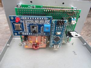
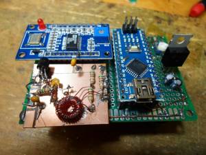
I intially used a UNO R3 board for develpoment, but used a NANO board for the final assembly. The schematic show wiring for the NANO board. Because the AD9850 and the LED back lighting of the display use a fair amount of current, a seperate 5V regulator is used to power these devices, rather then using the 5V regulator on the NANO board, as it would likely get very hot.
There are two types of AD9850 DDS modules available from China. I used the one with the two rows of 20 header pins and looks like a large DIP IC. If you use the other flavor, just follow the hook up diagram to connect to the required pins. These DDS modules are running about $10 at the time of this writing. Pretty amazing since the AD9850 chip costs $21 if you bought it all by it's self.
The LCD is a common 2 line, 16 character display. The ones with blue back lighting are very common and inexpensive. These run about $3.
All three of these major components can be obtained inexpensively direct for China buying with ebay. It just takes a few weeks to get them. If your in more of a rush, banggood.com can ship these from a US warehouse for a small price premium.
The rest of the discrete parts needed to build the SWR bridge and indicator can be obtained for the usual sources like Mouser or Jamesco. The MSP5179 transistors have a 1 GHz hft, so they still have decent gain at 28 MHz. You could sub the more common 2N3904's but it won't be as sensitive on the higher bands or may not work at all. If the LED does not light or is very dim at the higher frequencies, you don't have enough gain.
Since most of the componets are modules, I buit the project on a piece of FR4 pref board, using SIP sockets for the modules to plug into. The SIP sockets come in 40 pin strips. To cut them down to size, remove the pin one location past the number of pins you need and cut that slot with an hobby knife of razor saw. I use #28 heat stripable magnet wire to make all the interconnections. That way I don't need to strip insulated wire and makes for a neat looking wiring job.
The SWR bridge and amplifier could have been wired up right on the perf board, but I built it on a small scrap of copper clad board, dead bug style, which is a bit quicker and easier way to build it.
For final packaging, I recycled an old Radio Shack enclosure. Since the front panel of this box already had a number of holes in it (all in the wrong places, except for the display window, which was cut for a smaller display) I had to cover the old holes up somehow. I did this by simply putting down some double sided tape on the panel and then laid down a piece of black contruction paper and trimmed it to fit. This is then covered with a thin piece of clear Polycarbonate, which is easy to work with.
Programming the Arduino and the program "Sketch":
Hopefully your already familiar with the Arduino. If not a simple web search will come up with linksto the official Arduino web site with all the info you need.
The Sketch which you need is located in this zip file: Arduino_9850_sketch.zip
Once the Sketch has been downloaded into the Arduino board and everything is wired up, you will have to make one adjustment on the DDS module board. With the "unknown" leg of the bridge open, adjust the little trimmer resistor on the 9850 module until the SWR indicator LED comes on brightly. This trimmer sets the duty cycle of the square wave output and you want it more or less centered at 50%, but without a 'Scope just set it in about the middle of the adjustment range which makes the SWR LED stay on.
Parting thoughts:
This is my first Arduino "Sketch" and I'm pretty amazed I was able get it to work. I did take some late nights just to figure out how to do some simple things. I normally program directly in assembly which makes a whole lot more sense to me and is vasty more memory efficient and faster.
Although I designed this for the SWR bridge application, it can also be used as a signal generator, a transmitter VFO or even the VFO for a transceiver, although some modifications to the Sketch will be required for other applications.
For use as a signal generator with full tuning range, comment out the band limit tests in the DDSincerment() and DDSdecerment() routines and enable the max freq and min freq limits instead.
For a transceiver, you can add or subtract an offset to the base frequency before loading the DDS chip.
Anyway, I hope someone finds this project useful.
73, Steve KD1JV
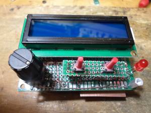
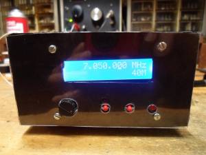
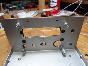
Virtual Radio Challenge
با سلام و تسليت ايام جانسوز رحلت رسول اكرم صلي الله و عليه واله وسلم
و امام حسن مجتبي عليه السلام و امام رئوف رضاعليه السلام
اخيرا در مسابقه اي كه در امريكا برگزار شده بود يكي از دوستان آقا مهدي از اعضاي گروه راديو اماتور البرز برنده آن شدند
توضيحات اقا مهدي راجع به مسابقه:
این مسابقات، نوعی چالش برای شبیه سازی کاربرد دستگاه های رادیویی/مخابراتی در مواقع بحران هست. اگر دو لینک فوق رو بخونید، کامل هستن.
یعنی یک سناریوی فرضی مطرح میشه (مثلا زلزله) که در اون زیرساخت های کشور مثل موبایل و تلفن و اینترنت و حتی بعضا برق دچار آسیب جدی شدن. حالا میگه شما برای برقراری ارتباط با دیگران و تماس با اون ها و همچنین گوش دادن به اخبار، از چه ابزاری استفاده می کنید. البته محدودیت هایی مثل محدودیت قیمت هم میذارن
علت برنده شدن من، دید متفاوت به این قضیه بود (همیشه برنده ها میان یه چیزی مثل یائسو ۸۱۷ رو میگن و خلاص. من سعی کردم از بعد دیگری به قضیه نگاه کنم و جامع تر توضیح بدم)
ممنونم دکتر. این مسابقات، نوعی چالش برای شبیه سازی کاربرد دستگاه های رادیویی/مخابراتی در مواقع بحران هست. اگر دو لینک فوق رو بخونید، کامل هستن.
یعنی یک سناریوی فرضی مطرح میشه (مثلا زلزله) که در اون زیرساخت های کشور مثل موبایل و تلفن و اینترنت و حتی بعضا برق دچار آسیب جدی شدن. حالا میگه شما برای برقراری ارتباط با دیگران و تماس با اون ها و همچنین گوش دادن به اخبار، از چه ابزاری استفاده می کنید. البته محدودیت هایی مثل محدودیت قیمت هم میذارن
علت برنده شدن من، دید متفاوت به این قضیه بود (همیشه برنده ها میان یه چیزی مثل یائسو ۸۱۷ رو میگن و خلاص. من سعی کردم از بعد دیگری به قضیه نگاه کنم و جامع تر توضیح بدم)
http://swling.com/blog/2015/12/winners-of-the-virtual-radio-challenge-iv-emergency-radio-preparedness/
http://ephamradio.com/forum/showthread.php?t=430
آزمون رادیو اماتوری
با سلام
سازمان تنظیم مقررات یا همان رگولاتوری قصد برگزاری آزمون رادیو آماتوری در سال جاری را دارد.
از علاقمندان درخواست می شود با تلفنهای سازمان یا سایت www.cra.ir تماس گرفته و ثبت نام نمایند
فرم های درخواست در سایت زیر موجود است:
www.ephamradio.com
با سلام
مطلبی راجع به فرستنده ساده 5واتی در رنج 7 مگابود جالب بود تقدیم می کنم
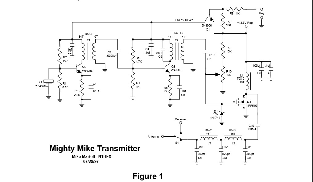
BUILD A 5 WATT 40 METER TRANSMITTER
As ham operators, we like to broaden our horizons by trying something new. There is nothing more
satisfying about this hobby than building your own transmitter. The circuit in figure 1 is a crystal
controlled CW transmitter with at least 5 watts of power. (The prototype generated 7 ½ watts) This
circuit was built on a Radio Shack universal board(276-168B) and worked extremely well the first time on
the air.
This circuit is unique in that it uses a power mosfet as a final rather than a conventional bipolar transistor.
The advantages are as follows:
a.)
Very high gain with almost 90% efficiency. (Only a small heat sink is required.)
b.)
Resistant to high SWR. 30 second key down with no antenna resulted in no dama
ge.
c.)
Power mosfets do not exhibit thermal runaway as with bipolar devices.
The disadvantages are that a bias voltage is required because the Gate threshold voltage can be
anywhere between 2 and 4 volts for any power mosfet. This bias must be adjusted for the particular
transistor installed in the circuit. In addition, a Zener diode is required to insure that the Gate voltage
never exceeds 20 volts. This circuit proves that the advantages far outweigh these requirements.
The adjustment of the bias voltage is critical and is adjusted by first turning R10 so that zero volts
appears on the Gate of Q4. Install an ammeter to the 13.8 volt supply voltage and apply power. At this
point the circuit should only be drawing just under 1 milli-amp. Now turn R10 slowly until the ammeter
reads about 5 milli-amps. This adjustment should never exceed 10 milli-amps. Turning R10 up too high
can cause damage to the power mosfet. Once adjusted, R10’s setting remains the same unless Q4 is
replaced.
All transistors can be purchased at Radio Shack and should not be substituted. Crystal Y1 is a 7.040
MHz crystal and can be purchased from Dan’s Small Parts & Kits or from Doug Hendricks. Send $3 to
Doug Hendricks, 862 Frank Ave., Dos Palos, CA 93620. (Specify 7.040MHz or 7.122MHz.) A small
heat sink is required for Q3 and Q4. S1 switches between transmit and receive modes so that no
damaging RF gets to the receiver being used. The frequency is fixed but a trimmer capacitor can be
installed in parallel or series with Y1 to allow some adjustment of frequency. Toroids can be purchased
from Dan’s Small Parts & Kits or from Palomar Engineers.
DE N1HFX
Parts List
R1
5.6K Resistor (Green, Blue, Red) ¼ watt
R2
15K Resistor (Brown, Green, Orange) ¼ watt
R3
2.2K Resistor (Red, Red, Red) ¼ watt
R4,R8
1K Resistor (Brown, Black, Red) ¼ watt
R5
4.7K Resistor (Yellow, Violet, Red) ¼ watt
R6
22 ohm Resistor (Red, Red, Black) ¼ watt
R7,R9
10K Resistor (Brown, Black, Orange) ¼ watt
R10
10K Trimmer pot, ¼ watt or larger
C1
.
01uf Ceramic disk capacitor
C2,C4,C6,C9
.1uf Ceramic disk capacitor
C3
.0028uf Ceramic disk capacitor (Use two .001uf capacitors and one 820pf
capacitor in parallel.)
C5
68pf Ceramic disk capacitor
C7,C10
.001uf Ceramic disk capacitor
C8
100uf electrolytic capacitor. (observe polarity)
C11,C13
390pf Silver Mica capacitor
C12
820pf Silver Mica capacitor
D1
15 volt Zener diode. 1N4744 or similar.
Y1
7.040 MHz or 7.122 Mhz crystal
T1
T50-2 toroid. 34 turns #26 wire for primary. 6 turns #22 wire for
secondary.
T2
FT37-43 toroid. 14 turns #26 wire for primary. 4 turns #22 wire for secondary.
L1
T68-2 toroid. 10 turns #22 wire.
L2,L3
T37-2 toroid. 16 turns #26 wire.
Q1
2N3906 transistor
Q2
2N3904 transistor
Q3
2N3053 transistor. Must use TO-39 or similar type heat sink.
Q4
IRF510 Power Mosfet transistor. Must use TO-220 heat sink(276-1363).
S1
Any suitable SPDT switch
آنتن اچ اف تمام باند
سلام بر دوستان و سروران
با تبريك فرار رسيدن عيد سعيد فطر
اين آنتن توسط شركت alibaba بقيمت 62 دلار فروخته مي شود
Description:
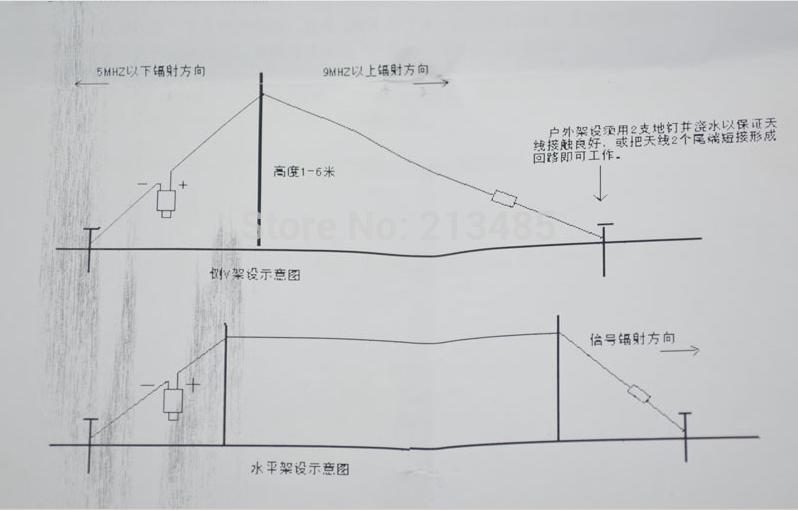
widely used in military , water and so on emergency communications using antenna concealment , easy to set up , no debugging , do not need tune -day , you can work the whole paragraph 1.5-30mhz ,0 -500 km without blind , the effective distance and inverted v antenna rather, in the range of 1000 kilometers effective communication . " Even for those who do not can not be set back v friend, because it can be set up in various forms , can be horizontal , inverted v, triangle , the frame line , stayed out of the window and so on. Outdoor set up, more convenient , readily detected at the roadside to 0.5 meters above the length of the antenna above the tree branches propped up on it , the location could not straighten the antenna , there is no problem , let go antenna Raowan type can be, one minute to get the antenna erection ! ! Is installed outdoors and special environment set up radio stations is a good helper ! ! !
Recently , concerns, and I like this antenna more people, but there is a need to make a grant to a friend now ! This antenna is very easy to set up , one person one minute can be set up is good, but the antenna is not required to debug , from 1.5 mhz - 30mhz standing waves are very ideal height from the ground is also not strictly required, more than 0.5 meters above the ground can be worked , outdoor gantry I also like to use it to do qso
1. Rated power : 100w, Operating frequency : 1.5-30mhz, transmit VSWR <2.0
2. the choice of brand GB black soft copper , hidden better
3 which batches of bigger and better selection of ring , so that argument is more ideal point oh ! Oh, can withstand high power 200W ( production , 200W high power for a long time to go through the test ) .
7Mhz short ended antenna
با سلام
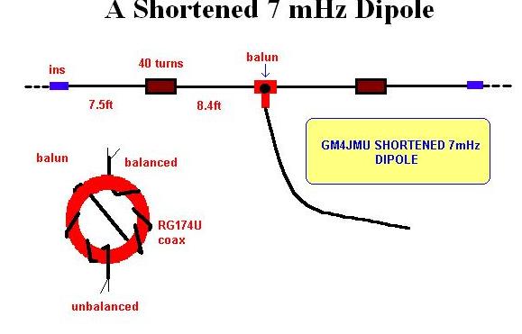
آنتن 7 مگا كوتاه شده براي پورتابل و اپارتمان
The shortened dipole for 7 mHz was described by Ken GM4JMU in Sprat 74. It is made from insulated wire - Ken used 24/0076. The coils are wound on 40mm ferrite as above, with 40 turns of the same wire on 1.5 ins PVC tube and may be water proofed if required. The balun at the centre is wound with miniature coax (RG174U). Tuning is best done in the clear and the preferred method of adjusting to resonance employed..
The same idea can be used to provide a mult-band doublet, by substituting tuned feeder for the coax.
The dipole described would be useful for the amateur with limited space and also for portable use.
lf radio in europe
سلام
امروز با web sdr در باند 100 تا 300 كيلو مي گشتم اين راديوها را ديدم تعجب كردم
اينهم زير 100 كيلو هرتز
pixie
- Pixie kit prices – truly incredible prices
Since my post earlier on this blog about low cost 40m Pixie kits from the Far East, I have been told that Bangood was selling these kits today for a staggeringly low price! This information is thanks to Spence M0STO. Earlier they were for sale at an incredible £2.67.
At this price you might just buy the crystal here in the UK! The kit comes with ALL parts (apart from battery, key and headphones) and a very nice silk-screened PCB. Don't forget this is with FREE shipping. Unbelievable.
My kit from them worked first time. It was the first time I'd built anything in a LONG time because of my stroke. At this price it is an offer too good to turn down. AM breakthrough was perfectly usable (i.e. low) and RX sensitivity fine. I got over 400mW out too. Don't forget, this is a complete 40m CW transceiver.
Sorry for the double post but the kits are here and the Customer Service is second to none. Beware the prices change daily inline with currency. http://www.banggood.com/DIY-Radio-40M-CW-Shortwave-Transmitter-Kit-Receiver-7_023-7_026MHz-p-973111.html
روز جهاني ارتباطات
با سلام و تبريك مبعث پيامبر مهر و رحمت محمد مصطفي (ص)
فردا روز جهاني ارتباطات و مخابرات در شبكه راديوئي جوان از ساعت 9 الي 10 صبح ويژه برنامه اي در برنامه كاوشگر جوان برگزار مي شود فركانس 88 مگا هرتز FM
از همه دوستان و علاقمندان راديو آماتوري دعوت مي شود با حضور خود در اين برنامه و تماس يا پيام يا يا مراجعه به سايت و يا به هر طريق ممكن علاقه و ابراز وجود و تمايل و طرفداري و اشتياق خود را به راديو آماتوري به نمايش بگذارند
به اميد شنيدن صداي گرم و ديدن پيام هاي شما عزيزان در اين برنامه
استقبال و علاقمندي و شركت در اين برنامه امكان تداوم آنرا مهيا ساخته و در پيشبرد و روشن شدن راديو اماتوري كمك فراوان خواهد كرد
با تشكر
عبدالحق
اولين راديو آماتور
با اطلاعات موجود اولين راديوآماتور جهان پروفسور هيوز انگليسي است كه در سال 1879 سالها قبل از هرتز، ماركني و ديگران اولين فرستنده و گيرندههاي راديويي تا حدود 200 متر برد را آزمايش نمود. ولي بطور عمومي ماركني مخترع راديو محسوب ميگردد كه در سال 1896 اولين سيستم راديويي را ثبت نمود و در سال 1897 برد حدود 14 كيلومتر سپس 140 كيلومتر را آزمايش نمود و با مخابره يك حرف مورس از انگلستان تا شمال كانادا (نيوفوندلند) در سال 1901 عصر راديو را عملاً آغاز نمود.
زندگي ماركوني
از ویکیپدیا، دانشنامهٔ آزاد
|
گولیلمو مارکونی |
|
|
متولد |
۲۵ آوریل ۱۸۷۴ |
|
مرگ |
۲۰ ژوئیه ۱۹۳۷ میلادی (۶۳ سال) |
|
ملیت |
|
|
رشته فعالیت |
|
|
دلیل شهرت |
اختراع سیستم بیسیم تلگرافی یا همان رادیو |
|
جوایز |
مدال فرانکلین (۱۹۱۸) |
گولیلمو مارکونی (به ایتالیایی: Guglielmo Marconi)∗ (۲۵ آوریل ۱۸۷۴ - ۲۰ ژوئیه ۱۹۳۷) مهندس برق ایتالیایی و دریافتکننده جایزه نوبل بود که در گسترش سیستم بیسیم تلگرافی یا همان رادیو تاثیر بسیاری داشت. مارکونی رئیس [۱] و عضو شورای عالی فاشیستی ایتالیا بود.[نیازمند منبع]
محتویات
- ۱ ابتدای زندگی
- ۲ تأسیس کمپانی مارکونی
- ۳ یک فرضیه با اثبات تجربی
- ۴ مخابره اولین پیام تلگرافی و امواج کوتاه
- ۵ کشف امواج کوتاه
- ۶ زندگی شخصی
- ۷ تصورات نادرست
- ۸ پانویس
- ۹ پانویس
- ۱۰ منابع
ابتدای زندگی
گوگلیلمو مارکونی در شهر بولونیای ایتالیا زاده شد. وی دومین پسر خانواده جوزپه مارکونی و آنی جیمسون که از خانوادههای اشراف و متشخصین ایتالیا به شمار میرفتند، بود. مادرش آنی دختر آندرو جیمسون از نوادگان دافنه[۲] در وکسفورد[۳] ایرلند برای خود تاریخچه بزرگی خانوادگی داشت.
مارکونی به طور خصوصی درس خواند و تحصیلاتش را زیر نظر آموزگاران کارکشته ایتالیایی در بولونیا و فلورانس ادامه داد. به عنوان یک پسربچه علاقه زیادی به فیزیک و علوم الکترونیکی داشت و کارها و پژوهشهای کسانی مانند ماکسول، هرتز و دیگران را بررسی و مطالعه میکرد.
در سال ۱۸۹۵ تجربیات و فعالیتهای آزمایشگاهی اش را در آزمایشگاه پدرش در پونتچیو[۴] شروع کرد جایی که اولین سیگنالها و نشانههای رادیویی تلگراف بیسیم را در فاصله یک و نیم مایلی مخابره کرد. در سال ۱۸۹۶ مارکونی تجهیزات آزمایشگاهی خود را به انگلیس آورد و در آنجا با سر ویلیام پریس[۵] مهندس الکترونیک اداره پست آشنا شد و بعد از یک سال حق ثبت امتیاز نخستین سیستم تلگراف بی سیم را دریافت کرد و این اختراع را به نام خود ثبت کرد.
تأسیس کمپانی مارکونی
یکی از دستگاههای فرستنده رادیویی مارکونی او با موفقیت تمام سیستم مخابره بی سیم خود را در لندن بین ایستگاه مخابراتی [۶] و بریستول[۷] در معرض نمایش گذاشت و در ژولای ۱۸۹۷ کمپانی تلگراف بی سیم و سیگنال[۸] &[۹] را با مسوولیت محدود تأسیس کرد. این شرکت در سال ۱۹۰۰ به کمپانی تلگراف بی سیم مارکونی تغییر نام داد. در همان سال سیستم بی سیم خود را در حضور مقامات دولتی ایتالیا در [۱۰] به معرض نمایش گذاشت. این نمایش در ایتالیا در فاصله ۱۲ مایلی انجام شد که رکوردی چشمگیر تا آن زمان بود.
در سال ۱۸۹۹ ارتباط تلگراف بی سیم میان دو کشور فرانسه و انگلیس برقرار شد. او ایستگاههای بی سیم ثابتی را در نیدلز،[۱۱] ایسل آو ویت،[۱۲] بورن موث[۱۳] و پس از آن در هاون هتل،[۱۴] پول[۱۵] و دورست[۱۶] ایجاد کرد. وی همچنین در سال ۱۹۰۰ شماره مشهور ۷۷۷۷ را برای امتیاز مخابرات بی سیم هم فرکانس را به نام خود ثبت کرد.
یک فرضیه با اثبات تجربی
در دسامبر سال ۱۹۰۱ او توانست فرضیه امواج رادیویی که تحت تأثیر چرخش زمین و در مدار آن قرار نمیگرفتند را اثبات کند. او با بیان این فرضیه اقدام به مخابره کردن اولین سیگنالهای امواج رادیویی در اقیانوس اطلس میان پولدهو،[۱۷] کورن وال[۱۸] و سنت جونز،[۱۹] نیوفوندلند به فاصله ۲۱۰۰ مایلی مخابره کرد.
سالهای ۱۹۰۲ تا ۱۹۱۲ او اختراعات دیگری را به ثبت رساند. در ۱۹۰۲ در طول سفر دریایی خود به فیلادلفیای آمریکا تأثیرات روشنایی روز و ارتباط مستقیم آن با ارتباطات و امواج بی سیم را کشف کرد و در همان سال امتیاز استاندارد امواج رادیویی شد ثبت نمود. این گیرنده برای سالهای طولانی یک الگوی استاندارد و جامع بود.
مخابره اولین پیام تلگرافی و امواج کوتاه
مارکونی به همراه همسر دوم و فرزندشان در دسامبر ۱۹۰۲ او اولین پیغام کامل تلگرافی را از ایستگاههایی در گلاس بی،[۲۰] نووا اسکوشیا[۲۱] و پس از آن [۲۲] و ماساچوست به پولدهو[۲۳] مخابره شد. این آزمایشها در سال ۱۹۰۷ در آیین گشایش نخستین سرویس بازرگانی آن سوی اقیانوس اطلس بین گالاس بی و کلیفدن[۲۴] ایرلند به اوج خود رسید.
این ماجرا پس از آن بود که نخستین سرویس همگانی تلگراف بی سیم در فاصلهای کوتاهتر میان باری در ایتالیا و مونتهنگرو برقرار شد.
مارکونی در سال ۱۹۰۵ امتیاز آنتن هوایی رادیویی را نیز به نام خود ثبت کرد. در سال ۱۹۱۴ به عنوان ستوان ارتش ایتالیا و پس از آن درسال ۱۹۱۶ در سمت ناخدای ناوگان ایتالیایی و سرکرده آنان، در ارتش خدمت کرد.
در سال ۱۹۱۷ او عضو هیئت اعزامی ایتالیا به آمریکا بود و در سال ۱۹۱۹ به عنوان نماینده کنفرانس صلح پاریس شرکت کرد. او نشان افتخار ارتش ایتالیا را به خاطر خدمت صادقانه به ارتش این کشور در سال ۱۹۱۹ دریافت کرده و طی سالهای خدمت در ارتش به پژوهش در مورد امواج کوتاه ادامه داد و اولین آزمایشها پیرامون این امواج را به طور عملی انجام داد، در سال ۱۹۲۳ با همکارانش در انگلیس به آزمایش روی این سری از امواج پرقدرت میان ایستگاه رادیویی پولدهو و قایق تفریحی مارکونی که در آتلانتا و مدیترانه بود پرداخت.
پیشنهادهای استفاده از این سیستم به معنای امپراتوری باشکوه ارتباطات بود که از سوی دولت انگلستان پذیرفته گشت و بدین ترتیب اولین ایستگاه ارتباطی میان انگلیس و کانادا در سال ۱۹۲۶ شکل گرفت و ایستگاههای بعدی متعاقباً در سالهای بعد اضافه شدند.
کشف امواج کوتاه
در سال ۱۹۳۱ مارکونی پژوهشهای گسترده خود را درباره انتشار گسترده امواج کوتاه از سر گرفت که نتیجه آن در سال ۱۹۳۲ در قالب اولین تلفن بی سیم که از امواج کوتاه الکترومغناطیسی بهره میبرد ارائه داد که میان واتیکان رم و کستل گاندولفو،[۲۵] شهری که پاپ تابستانها در آنجا مستقر بود بکار گرفته شد. دو سال بعد در سستری لوانته[۲۶] امواج کوتاه رادیویی که برای هدایت کشتی کشف کرده بود را در برابر نیروی دریایی به معرض نمایش گذاشت. او پس از این اختراعات، مدرک دکترای افتخاری دانشگاههای بسیاری را در سراسر اروپا کسب کرد و در مجامع جهانی جوائز و افتخارات زیادی را به نام خود ثبت نمود که از میان آنها میتوان به جایزه نوبل با مشارکت فردیناند برون در فیزیک در سال ۱۹۰۹، نشان آلبرت از جامعه سلطنتی هنری،[۲۷] نشان جان فریتز،[۲۸] نشان کلوین[۲۹] و ... اشاره کرد.
او همچنین از طرف تزار روسیه نیز مفتخر به کسب عنوان شد و حتی از سوی سنت آن،[۳۰] پادشاه ایتالیا به لقب فرمانده ارشد نایل آمد. بسیاری دیگر نیز در همان زمان به استعداد و نبوغ او واقف بودند. در ۱۹۱۴ او در مجلس سنای ایتالیا به مقام سناتوری رسید و در انگلستان به عنوان یک نجیب زاده در [۳۱] به شهرت رسید و پس از آن در سال ۱۹۲۹ به عنوان موروثی مارچس[۳۲] دست پیدا کرد.
زندگی شخصی
در سال ۱۹۰۵ با بئاتریس اوبرین[۳۳] دختر بارون چهاردهم اینچیگوئین[۳۴] ازدواج کرد. ازدواجی که تا ۱۹۲۷ بیشتر دوام نداشت و در همان سال با کنتس بتزی-اسکالی[۳۵] از شهر رم پیمان زناشویی بست. مارکونی از ازدواج اولش یک پسر و دو دختر داشت و از همسر دومش فقط صاحب یک دختر شد. تفریح او در زمان فراغتش شکار، دوچرخه سواری و خودرورانی بود. وی در نهایت در ۲۰ ژوئیه ۱۹۳۷ در رم درگذشت.
تصورات نادرست
گولیلمو مارکونی رادیو را اختراع نکرد بلکه آنرا برای ارتباطات و بکارگیری عمومی گسترش داد.[۳۶] در تاریخ از شخص خاصی به عنوان مخترع رادیو نام برده نشدهاست.
پانویس
^ در زبان ایتالیایی ترکیب gli «لیی» تلفظ میشود.
ماركوني
زندگینامه گوگلي المو ماركوني مخترع راديو
ملیت : ایتالیا - قرن : 19
گوگلي المو ماركوني مخترع راديو در سال 1874 در شهر بولوني ايتاليا به دنيا آمد. او از خانوادهاي مرفه بود و معلمان و مربيان خصوصي تعليم و تربيت او را به عهده داشتند.ماركوني در سال 1894 و به سن بيست سالگي مطالبي درباره آزمايشهاي انجام شده توسط هنريش هرتز خواند. آن آزمايشات به وضوح وجود امواج نامرئي الكترومغناطيسي را كه با سرعتي معادل سرعت نور در فضا حركت ميكردند، نشان داده بود.
بلافاصله اين فكر براي ماركوني پديد آمد كه ميتوان بدون استفاده از سيم از اين امواج براي فرستادن علائمي به فواصل دوردست بهره گرفت. اين امر امكاناتي را براي ارتباطات فراهم ميكرد كه در استفاده از تلگراف با سيم ميسر نبود. از جمله اينكه با اين روش ارسال پيامها براي كشتيهاي در حال حركت در درياها ممكن ميشد.
تا سال 1895 تنها با يك سال تلاش ماركوني موفق شد وسيله لازم براي اين كار را بسازد. در سال 1896 ماركوني وسيله مزبور را در انگلستان به نمايش گذاشت و توانست اولين امتياز انحصاري اختراع خود را دريافت نمايد. ماركوني سريعاً يك شركت تأسيس كرد و در سال 1898 اولين راديوگرام (ماركوني گرام) ارسال شد.
سال بعد او توانست پيامهاي بيسيم را به آن سوي كانال مانش بفرستد. با اينكه در سال 1900 مهمترين امتياز خود را دريافت نمود ولي همچنان به كار خود ادامه داد و براي بهبود و تكميل اختراع خود تلاش كرد. در 1901 او موفق شد يك پيام راديو به آن سوي اقيانوس اطلس، از انگلستان به نيوفونلند، بفرستد.
اهميت اين اختراع جديد در يك حادثه غمانگيز به خوبي آشكار گرديد. در سال 1909 كشتي «اس.اس.ريپوبليك» در تصادفي صدمه ديد و غرق شد. از طريق پيامهاي راديويي كمك خواسته شد و تمام سرنشينان كشتي بجز 6 نفر نجات يافتند. در همين سال ماركوني به خاطر اختراعش برنده جايزه نوبل شد. در سال بعد ماركوني موفق شد پيامهاي راديويي را از ايرلبند به آرژانتين، يعنی مسافتي بالغ بر شش هزار مايل بفرستد.
تمام اين پيامها با روش خط و نقطه (مورس) فرستاده شده بود. اينك مشخص گرديد كه صدا را نيز ميتوان به وسيله راديو منتقل كرد. ولي اين كار تا سال 1915 عملي نشد.انتشارات راديويي در مقياس تجاري تنها در اوايل دهه 1920 آغاز گرديد ولي پس از آن خيلي زود توسعه يافت و همگاني شد.
اختراعي كه حقوق انحصاري آن فوقالعاده با ارزش بود بدون ترديد برخي درگيريهاي حقوقي و قضايي را برميانگيخت. اما تمام اين مرافعات و دادخواهيها با رأي صريح دادگاهها در سال 1914 مبني بر حق اولويت ماركوني به خاموشي گراييد.
در سالهاي بعد ماركوني تحقيقات مهمي در باب موج كوتاه و مخابرات مايكروويو انجام داد. او در سال 1937 در شهر رم درگذشت.
از آنجا كه ماركوني تنها به عنوان يك مخترع معروف ميباشد بديهي است كه تأثير او نيز مناسب با اهميت راديو و تبعات مستقيم آن خواهد بود. (ماركوني تلويزيون را اختراع نكرد اما اختراع راديو گامي مهم براي اختراع تلويزيون بود و بنابراين منصفانه خواهد بود اگر قسمتي از اعتبار اختراع تلويزيون به ماركوني داده شود). روشن است كه ارتباطات بيسيم در دنياي نوين از اهميت ويژهاي برخوردار است.
در انتقال اخبار براي سرگرمي و تفريح، مقاصد نظامي، تحقيقات علمي و انجام وظايف و بسياري موارد مقاصد ديگر از بيسيم استفاده ميشود. اگر چه براي برخي موارد ميتوان از تلگراف، كه نيم قرن قبل اختراع شده بود، استفاده مشابهي كرد اما در بسياري از موارد راديو بيرقيب است و چيزي را نميتوان جانشين آن كرد. با استفاده از آن ميتوان با اتومبيلهاي در حال حركت، كشتيها در درياها و هواپيماهاي در حال پرواز و حتي سفينههاي فضايي ارتباط برقرار كرد.
اختراع راديو بسيار مهمتر از اختراع تلفن ميباشد. پيامي كه با تلفن فرستاده ميشود با راديو نيز ميتوان ارسال كرد در حالي كه با راديو ميتوان با نقاطي ارتباط برقرار كرد كه امكان تماس تلفني وجود ندارد.
با توجه به اين نكته و از آنجا كه ارتباط بيسيم بسيار مهمتر از ارتباط تلفني است ماركوني در ردهاي بالاتر از گراهامبل قرار ميگيرد. اگر اديسون كمي بالاتر از ماركوني قرار داده شد به اين دليل است كه او صاحب اختراعات متعدد و زيادي بود هر چند هيچكدام از آنها به تنهايي اهميت و ارزش راديو را نداشتند.
از آنجا كه راديو و تلويزيون تنها قسمت كوچكي از موارد استفاده عملي از كارهاي نظري ماكسول وفاراده ميباشد بنابراين منصفانه است كه ماركوني پايينتر از آن دو تن قرار داده شود. اما با توجه به اينكه معدودي از بهترين چهرههاي سياسي تأثيري مشابه به تأثير ناركوني بر جهان داشتهاند بنابراين ماركوني را بايد سزاوار و شايسته رده بالايي در اين فهرست دانست.
منبع:rasekhoon.net
اختراع راديو
ماجراي اختراع راديو
از آزمايش موفقيت آميز هاينريش هرتس در سال ۱۸۸۸ مبني بر وجود و امکان ارسال و دريافت امواج راديويي تا زمان اختراع اولين راديوي واقعي، پله هاي پيشرفت يکي يکي طي شدند. آگوستو ريگي، فيزيکدان ايتاليايي، کار هرتس را فراتر برد و ثابت کرد که ارتعاش هاي الکتريکي و نوري هر دو از يک ماهيت هستند. در همان سال ۱۸۸۸دانشمند ديگري به نام تميستوکل کالزکي _ اونستي با اين باور که تخليه الکتريکي ناشي از آشفتگي هاي جوي بر براده هاي آهن اثر مي گذارد، يک تيوب(يا لامپ الکتروني) ساخت که اليور لاج در سال ۱۸۹۴ نام«کوهرر»(coherer) را بر آن نهاد و قدرت دريافت امواج هرتسي را به کمک آن افزايش داد. کار بعدي را الکساندر پوپوف روسي انجام داد. او اولين چيزي را که مي شود نام آنتن را به آن اطلاق کرد، با يک ميله فلزي قائم و اتصال آن به کوهرر لاج براي گرفتن و دريافت آشفتگي هاي جوي، برپا کرد. اختراع اين ابزارها سرانجام به گوگليلمو مارکوني امکان داد تا کشف تاريخي اش را به انجام برساند. او دريافت که امواج الکترومغناطيسي مي توانند بين دو نقطه که با مانعي از هم جدا شده اند، منتقل شوند. اين کشف سرمنشاء ساخت اولين فرستنده/گيرنده راديويي بود. او اولين آزمايش ارسال و دريافت امواج راديويي را در سال ۱۸۹۵ در ايتاليا انجام داد. در سال ۱۸۹۹ او توانست اولين سيگنال بي سيم را در عرض آبراهه انگليس منتقل کند.
دو سال بعد، در ۱۲ دسامبر ،۱۹۰۱ حرف«S» را که از انگلستان به نيوفاوندلند مخابره شده بود، دريافت کرد. اين اولين پيام راديوتلگرافي بود که با موفقيت بين دو سوي اقيانوس اطلس منتقل شده بود. به اين ترتيب، اولين آزمايش هرتس که با فاصله ۵/۱ متر بين گيرنده و فرستنده انجام شده بود، سرانجام به صدها کيلومتر رسيد و«راديوتلگرافي» يا ارسال و دريافت امواج راديويي بين نقاط مختلف، به واقعيت پيوست. اما با اين که اغلب مارکوني را مخترع راديو مي دانند، واقعيت آن است که نيکلاتسلا فيزيکدان آمريکايي زودتر از او به موفقيت دست يافته بود و اگر چند بدشانسي پياپي نبود، نام او به عنوان مخترع راديو در اداره ثبت اختراعات آمريکا به ثبت مي رسيد. گر چه سرانجام اين کار چند ماهي پس از مرگ او انجام شد. در سال ۱۸۹۵ در حالي که تسلا آماده مي شد يک سيگنال را به فاصله ۵۰ مايلي ارسال کند، آتش سوزي آزمايشگاهش کار را نيمه تمام گذاشت. در عين حال، او در سال ۱۸۹۷ درخواست ثبت اختراعات خود را تحويل اداره مربوطه کرد که در سال ۱۹۰۰ پذيرفته شد. تسلا دستگاه هايي ساخته و ابداعاتي انجام داده بود که مارکوني از همان ها براي تکميل راديوي خود استفاده کرده بود. اولين درخواست مارکوني در ۱۰ نوامبر ۱۹۰۰ به اداره ثبت اختراعات آمريکا داده شد اما پذيرفته نشد. طي سه سال بعد نيز مرتب درخواست هاي او به دليل آن که اختراعات تسلا و ديگران مقدم بر کار او بوده است، رد مي شد. اما«شرکت تلگراف بي سيم مارکوني» در سال ۱۹۰۰ شروع به شکوفايي در بازار بورس کرد و هر سهم آن از ۳ دلار به ۲۲ دلار رسيد، گر چه اين رشد به ارتباطات پشت پرده خانواده مارکوني هم بي ارتباط نبود. حتي اديسون در شرکت مارکوني سرمايه گذاري کرده بود و به او مشاوره مهندسي مي داد. در سال ۱۹۰۴ اداره ثبت اختراعات آمريکا تصميم هاي قبلي خود را ناديده گرفت و امتياز اختراع راديو را به نام مارکوني ثبت کرد. گر چه دليل اين تصميم هيچ گاه آشکار نشد، اما سرمايه هاي هنگفت بانکي شرکت مارکوني يکي از دلايل محتمل اين تصميم به نظر مي رسد. تسلا شايد زياد ناراحت نمي شد اگر ماجرا در همين حد باقي مي ماند، و البته آن قدر درگير مشکلات ديگر بود که فرصتي براي پي گيري آن نداشت. اما وقتي جايزه نوبل سال ۱۹۱۱ را به مارکوني دادند، خون تسلا به جوش آمد. او در سال ۱۹۱۵ به دليل استفاده بي اجازه از امتياز انحصاري ابداعات خود، از شرکت مارکوني شکايت کرد اما وضعيت مالي اش به او اجازه نداد تا شکايت خود را دنبال کند و در برابر اين شرکت عظيم بايستد. تنها سال ها بعد در ۱۹۴۳ بود که سرانجام دادگاه عالي امتياز اختراع راديو را که به شماره ۶۴۵.۵۷۶ به نام تسلا به ثبت رسيده بود، معتبر شمرد و مارکوني را از دور خارج کرد. البته اين راي دليلي تقريباً خودخواهانه داشت: شرکت مارکوني از دولت آمريکا به خاطر استفاده از امتيازهاي انحصاري خود در جنگ جهاني اول شکايت کرده بود و دادگاه به سادگي با دادن امتياز به نام تسلايي که حالا مرده بود و از ابتدا هم اولويت و حق با او بود، شکايت شرکت مارکوني را از موضوعيت انداخت.
نويسنده: علي اکبر قزويني
منبع: روزنامه شرق
web sdr
با سلام و تبريك ايام پربركت بعثت رسول اكرم صلي الله
اين ادرس گيرنده اينترنتي دانشگاه اوتونت هلنده
http://websdr.ewi.utwente.nl:8901/
اينم خود گيرنده است
اين پهناي باند اچ اف در ساعت 11 بعد از ظهر بوقت ايران در هلند و دانشگاه تونتو و انتن هم يك انتن ميني ويپ مي باشد
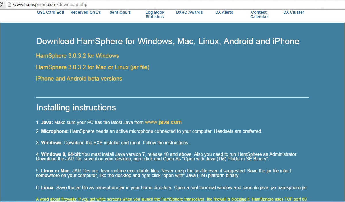
hamspher
با سلام
ذکر چند مطلب در مورد سایت هامس فر لازم است
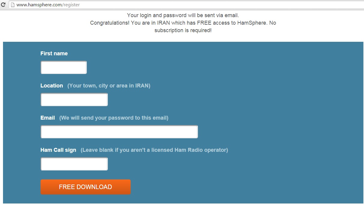
این نرم افزار برای ایران رایگان است بشرط:
فقط در کامپیوتر استفاده شود لذا نصب آن در گوشی و اجرای ان با نرم افزار وسیستم عامل موجود نسخه دمو یا اعتبار محدود می دهد و بعد باید هزینه پرداخت
حتما باید ادرس از ایران باشد لذا مواردی دیده شده دوستان از وی پی ان یا فیلتر شکن استفاده کرده اند و کاربریشان عوض شده و رمز شان غیر فعال گردیده است
این موارد بلا هائی بود که سر خود من آمد و با توضیح مطلب به مدیر سایت هامس فر موفق به فعال کردن مجدد کاربری خود شدم
برنامه خوبی است و دوستان علاقمند اگر از ان استفاده کنند مثل بازیها یا دمو های برنامه های جدی کار قشنگی خواهد بود
ضمنا جهت اطلاع این سایت از طریق ایستگاههایی که به SDR مجهز هستند به فضای واقعی و امواج مرتبط می شود و ایستگاههایی همین کار را کرده اند
HamSphere Country Mismatch
Your account 154HS230 was registered from IR and it has been used from RO with IP 5.254.97.100 therefore your account has been blocked.
You can fix this problem and re-activate the account by subscribing to HamSphere here:
http://www.hamsphere.com/subscribe.php?callsign=154HS230&rnd=ip
The account will be reinstated and activated immediately after the purchase and it can then be used anywhere in the world.
Kind regards
www.HamSphere.com
|
Inbox
|
x | |||
|
Apr 13 (5 days ago)
 |
|||
|
||||
کارت های تماس
با سلام و آرزوی سلامتی
تعدادی از کارتهایی که اخیرا بدستم رسیده جهت اطلاع در ذیل می اورم
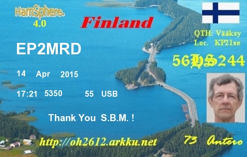
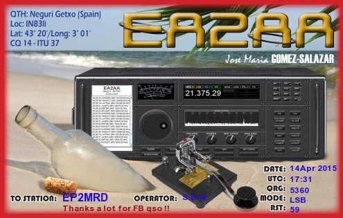
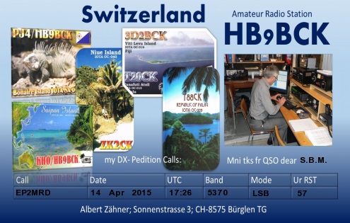
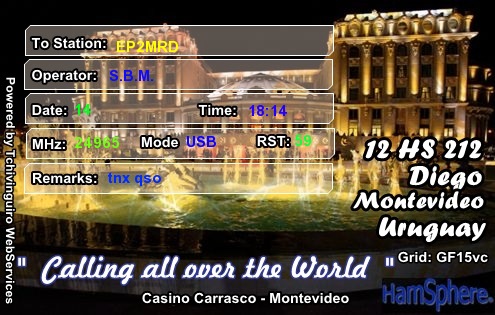
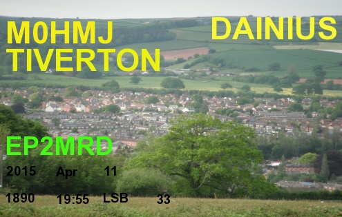
جالبه 1890کیلو بود نزدیک 2 نصفه شب
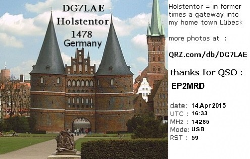
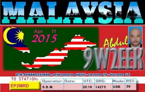
Hamspher
You live in a country with FREE access to the HamSphere PC Version. (Subscription is however necessary for mobile versions iOS / Android)
Please connect a microphone to your PC before starting the software. USB headsets work well!
HamSphere accepts both licensed Ham operators and unlicensed enthusiasts who have the intention of becoming licensed.
Unlicensed enthusiasts on HamSphere have a specific HS callsign based on the international country prefix index.
If you are a licensed Ham operator, we encourage you to guide, help and support the HS users on the system.
You should follow the Amateur Radio ethics on HamSphere:
* Always listen if the frequency is clear before you call. Be courteous!
* Always use your own callsign, either your HAM-call or approved HS-call.
* Call CQ on any frequency. There are no calling frequencies on the Ham Bands (except 27.555 MHz on 11m)
* Keep your modulation within the ALC level 3-5 for VOICE operation.
* Keep your modulation MAX ALC level 1.5 for CW operation with own sinewave oscillator.
* For CW operation, stay on 160, 80 and 30 meters..
* Use only as much power as you need to maintain a QSO depending on the propagation.
* Amateur Radio is commercial free. Absolutely NO Commercial ADVERTISING in Chat or Verbally. Failure to follow this directive will result in banning of your account.
On HamSphere we use the Amateur Radio Protocol which means: Always end your transmissions with:
"The callsign of the operator to speak next" followed by "this is" and "your callsign" and "over"
HamSphere Manual
http://www.hamsphere.com/5_5662_read.html
How to operate DX Pile-UPs (Important)
HamSphere is a Ham Radio transceiver with extended functionality such as:
- Use realistic SSB Shortwave propagation or reliable 2-meter FM like communications.
- 24H Support
- Send and receive QSL cards directly from the Transceiver
- Make your own QSL cards with our QSL-Card Editor
- Create your own Home Page based on your callsign
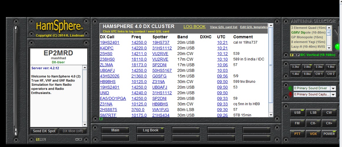
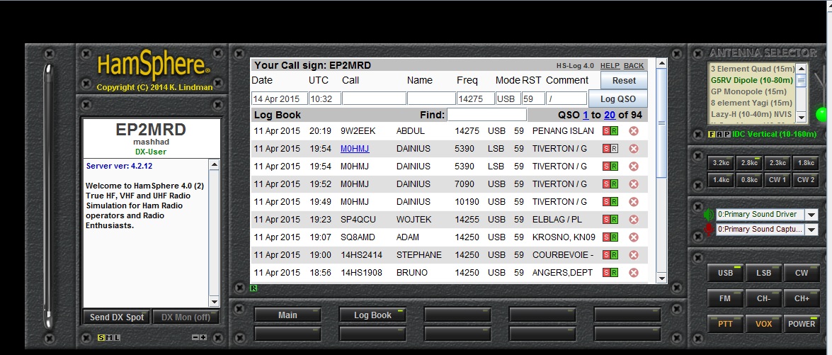
- Log your contacts with the integrated LOG-Book
- Use the DX-cluster to find Ham Radio operators all over the world
- Hunt for our prestigious DXHC-Awards
73 de Kelly 5B4AIT, Cyprus
Follow us on facebook
Follow us on Twitter
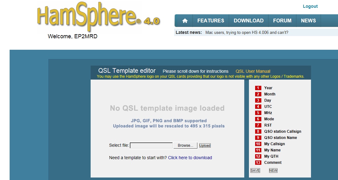
نحوه ساخت کارت تائیدتماس در همسفر
باسلام
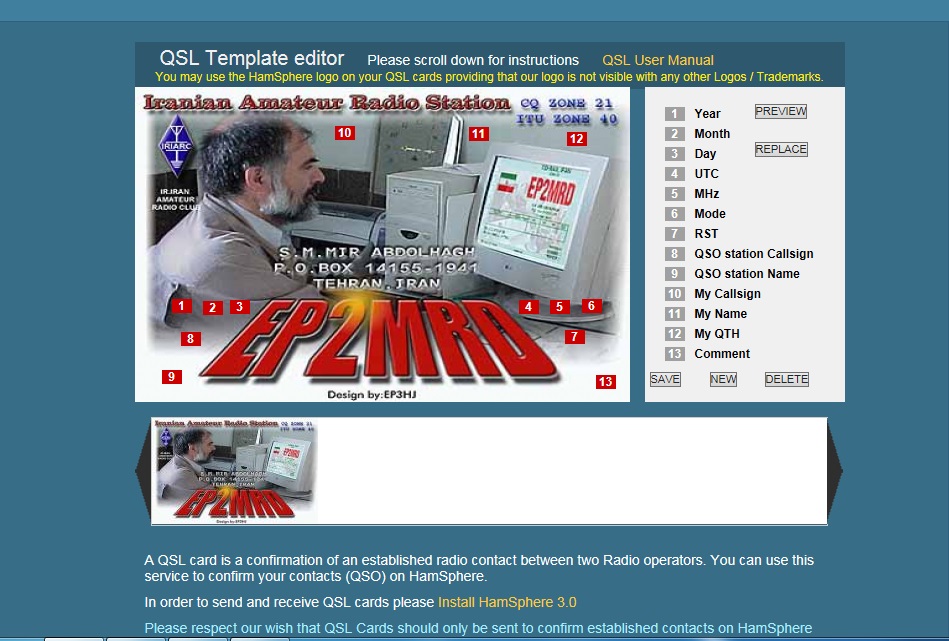
جهت تهیه کارت تائید تماس در همسفر ابتدا برنامه نصب و اجرا می شود

پس از نصب به بخش لوگ بوک رفته و پس از ورود به صفحه جدید آن گزینه ادیت را انتخاب می کنیم
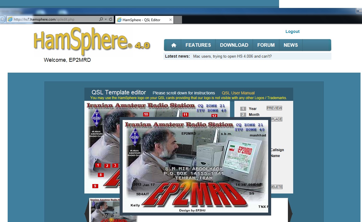
بعد نمونه را دانلود و ذخیره کرده و روی صفحه اول اورده و تک تک شماره هارا به محل خودش نصب می نمائیم
در پایان صفحه را ذخیره و از برنامه خارج می شویم
نمونه کار هم این گونه است
البته نمونه اصلی به اینصورت است
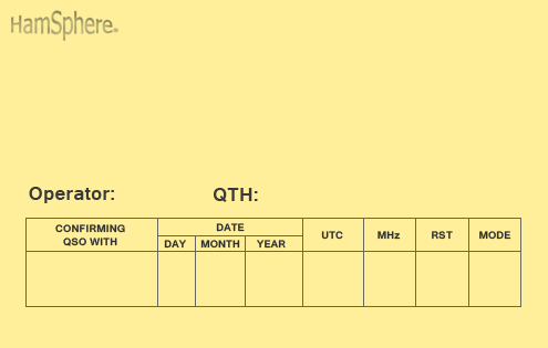
جهت درج کارت هم لیست کارتها را آورده و ارسال می کنیم
Hamsphare
با سلام و عرض ادب
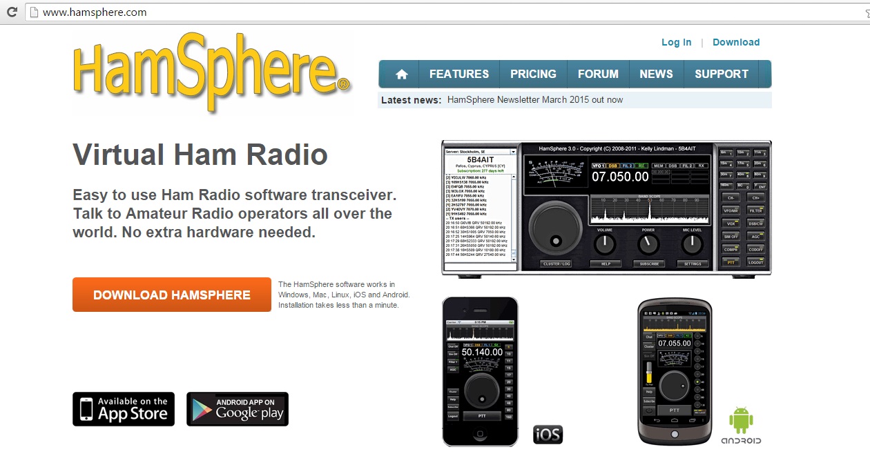
درمورد رادیوی اینترنتی بعد از مراجعه به سایت رادیو در ادرس زیر و دانلود برنامه ان بشرح زیر اقدام می شود
http://www.hamsphere.com/

ورود کاربران

عضويت سريع

پشتيباني آنلاين

آمار

خبرنامه

آخرین نطرات کاربران
 جواد یاور مطلق - درود
 بلا بدور باشه مهندس !
انشالله همیشه سرحال سالم تندرست باشید !
پاسخ:با درود و سپاس از لطف شما دوست گرامی بدرود - 1403/1/29
 یک هم وطن - من بدون مدار این رادیو ساختم باصدای واضح و بلند بدون برق و باطری
 پاسخ:باتشکر از لطفتان امیدوارم بقیه دوستان هم همت کنند و دست به اچار و هویه شده خودشان بسازند و لذت ساختن را ببرند چون در داشتن لذت نیست هنر ساختن است - 1402/6/13
 AEC - درود
استاد ممنون خیلی خوب و عالی
پاسخ:باسلام و تشکر از لطف و مرحمت شما دوست عزیز و گرامی - 1400/8/28
 پرویز مهرزاد - سلام ودرود استاد عبدالحق عزیز بسیار خوشحالم که سایت جنابعالی بامطالب جدید وعالی دوباره فعلیتش را شروع نموده است.
پاسخ:با سلام تذکر بجا و بموقعی بود بسیار متشکرم - 1400/8/28
 ایزدی - یه مشکلی داره این طرح. کل سلف ها با هم 12. 7 میکرو میشه که با خازن 270 پیکو، فرکانس مرکزی فیلتر 2.7 مگا هرتز می شه. کمترین سلف هم (0.1 میکرو) با همون خازن 270 پیکو 30 مگاهرتز رو رد می کنه. بنا بر این نیازی به خازن های دیگه نیست. دوستان دیگه نظرشون چیه.
پاسخ:باسلام و تشکر کل خازن ها و سلفها برای فرکانس 1800کیلو که ابتدای باند رادیو اماتوری است کم است و بسختی تنظیم می شود اما برای 3500 بله زیاد است - 1399/8/24
 هومن - سلام .علت استقبال نکردن در خور توجه همین نا واردیست .این مطلب بسیار گنگ و پر از اشتباه هست
 پاسخ: سلام بنده هم ضمن تائید نظر شما درخواست می کنم مطلب کامل تر و بهتر و درست تر را بفرمائید بنده بنام خودتان درج و منتشر نمایم
پاسخ:https://t.me/joinchat/AAAAAEJj30AwLGIyi_UQ3g مدارات لامپی - 1396/12/17
 علی - سلام شما مکتبی و انقلابی هستید درسته ؟
پاسخ: سلام بهیچ عنوان و تقریبا هیچ جائی من چنین ادعائی نکرده ام اما این همه شهید و زخمی و جانباز و اسیر و زحمت و فعالیت برای حفظ انقلاب و سرزمین عزیزمان ایران خیلی حرام لقه گی و بی اصل و نصبی می خواهد که چشم خودرا ببندیم و از این اب و خاک حمایت و به این مردم عشق نورزیم حالا شما اسم انرا هرچه دوست دارید بگذارید نظرتان محترم است - 1396/12/17
 هومن - سلام
 بنده یکی از علاقمندان لامپ هستم . و 10 سال اخیر را بر روی مدارات لامپی کار کردم .با سرچ اینجا را پیدا کردم .می خواستم ببینم در زمینه مخابرات فعالیت لامپی در ایران هست ؟
این مطلب راجب لامپ واقعا توجه مخاطب علاقمند را جلب می کند ؟
من فکر می کنم نویسنده اصلا راجب لامپ حس خوبی ندارد .عذر خواهی می کنم
پاسخ:سلام دوست عزیز از صراحت و فصاحت بیان شما خوشحالم مطلبتان راجع به نویسنده مطلب لامپ کمی کم لطفی و شاید سخت گیری در بر دارد نویسنده مطلب استاد عاملی بزرگ رادیو اماتوری ایران هستند و مطلب را بی اندازه ساده و اسان گفتند چون اکثر جوانها از لامپ و ولتاژ کار ان وحشت داشته و تقریبا هیچ نمی دانند اما ظاهرا شما در مورد لامپ مطلع و ازموده هستید لذا برخود نگیرید شما هم اگر در مورد لامپ و یا مطالب استاد عاملی نقد و نظری دارید بسیار خوشحال می شوم مکتوب بفرمایید تا در همان بخش یا در بخش جدید بنام خودتان منتشر شود
پاسخ:https://t.me/joinchat/AAAAAEJj30AwLGIyi_UQ3g - 1396/12/16
 سعیدی - سلام استاد بنده بی جواب ماندم
 پاسخ:با سلام و پوزش از تاخیر طبق تجربه دوستان این مدار به دلیل نامرغوب بودن قطعات نو موجود در بازار معمولا در ابتدا کار نمی کند لذا بتوصیه استاد عاملی بهنر است از قطعات اوراقی رادیو و ضبط ها استفاده شود قطعات معمولا در گیر این رادیو ابتدا ای سی سویچ یا کلید زنی است که یک مدل خاصش برای مدار مناسب است و مدلهای دیگر فرکانس کار و ولتاژشان مناسب نیست درمورد ای سی مدولاتور و دمدولاتور 3028 این ای سی هم بشدت مورد شک و شبهه است در موردی باتعویض 5 عدد ای سی دو عدد که بهتر بود در مدار بکار گرفته شد لذا بهترین روش استفاده از مرحله مرحله و گام بگام کار کردن رادیو است ضمن انکه اگر فرستنده کار بیفتد گیرنده هم کار خواهد کرد و بالعکس لذا شما می توانید مدار را از میکروفون در حالت فرستنده یا بلندگو در حالت گیرنده شروع نمایید و اگر مسیر سیگنال جدا باشد در نقشه شما می توانید از تقویت صدا شروع کرده و به دمدولاتور رفته و سپس به فیلتر و بعد میکسر وی اف او و در اخر به فیلتر تنظیم باند بروید و حد اکثر سیگنال و حساسیت را بدست اورید پس فیلتر های رادیویی یا بقول شما توکو ها قسمت اخر تنظیم و تعقیب مدارتان است اگر شد برای اطلاع شما و سایر دوستان مدار را در حالت گیرنده و فرستنده جدا اراعه خواهم داد یا با رنگ مسیر سیگنال را جدا می کنم که راحت تر باشد اگر شما عضو تلگرام هستید در یکی از گروه های رادیو اماتوری بیایید و مستقیما با دوستان سازنده و استفاده کننده رادیو تماس گرفته راهنمایی شوید اگر نه ادرس ایمیلتان را بدهید تا راهنمای مونتاژ را برایتان بفرستم
پاسخ:http://py2ohh.w2c.com.br/trx/ararinhamontagem/montandoararinha.htm
راحل مونتاژ و تست مدار است - 1396/11/5
آرشیو
- تير 1403
- مهر 1402
- ارديبهشت 1401
- دی 1400
- آبان 1400
- ارديبهشت 1399
- اسفند 1397
- آذر 1397
- آبان 1397
- خرداد 1397
- ارديبهشت 1397
- فروردين 1397
- اسفند 1396
- بهمن 1396
- دی 1396
- آذر 1396
- آبان 1396
- شهريور 1396
- مرداد 1396
- تير 1396
- خرداد 1396
- ارديبهشت 1396
- فروردين 1396
- اسفند 1395
- بهمن 1395
- دی 1395
- آذر 1395
- آبان 1395
- مهر 1395
- شهريور 1395
- مرداد 1395
- تير 1395
- خرداد 1395
- ارديبهشت 1395
- فروردين 1395
- اسفند 1394
- بهمن 1394
- دی 1394
- آذر 1394
- آبان 1394
- مهر 1394
- شهريور 1394
- مرداد 1394
- تير 1394
- خرداد 1394
- ارديبهشت 1394
- فروردين 1394
- اسفند 1393
- بهمن 1393
- دی 1393
- آذر 1393
- آبان 1393
- مهر 1393
- شهريور 1393
- مرداد 1393
- تير 1393
- خرداد 1393
- ارديبهشت 1393
- فروردين 1393
- اسفند 1392
- بهمن 1392
- دی 1392
- آذر 1392









 با سلام و ارزوی قبولی طاعات

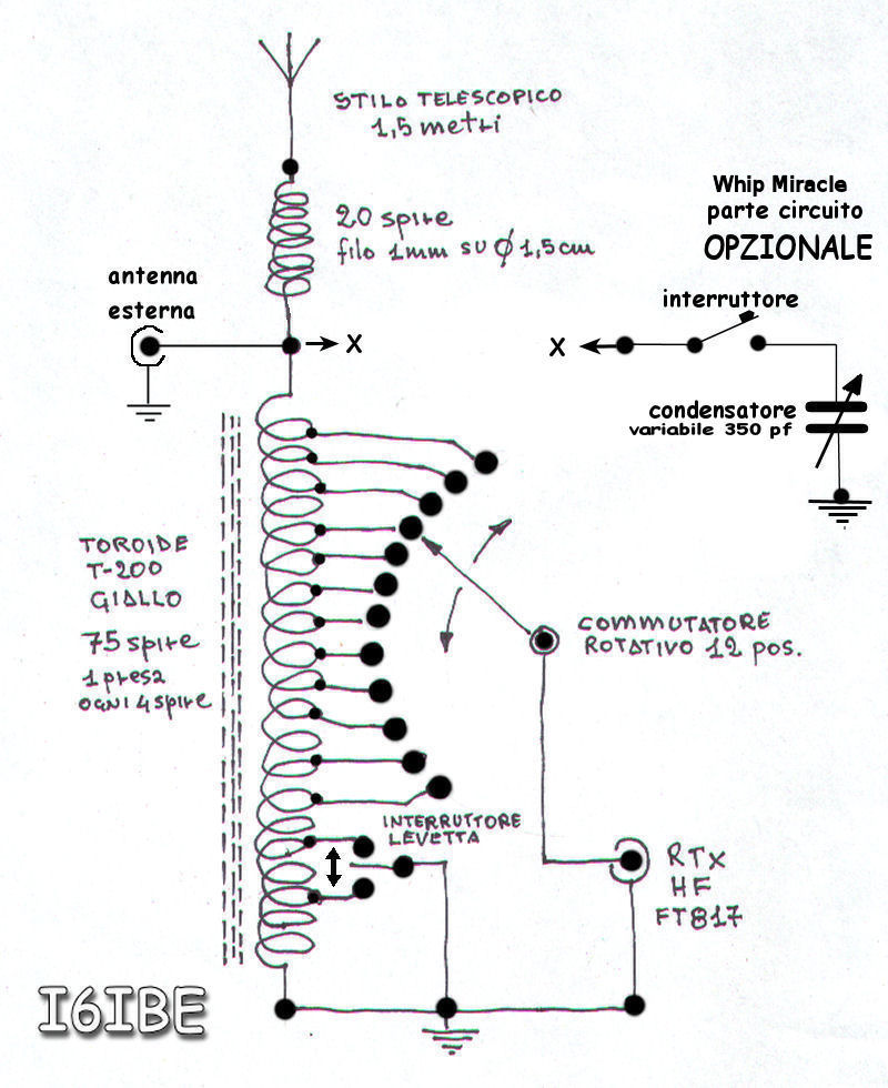
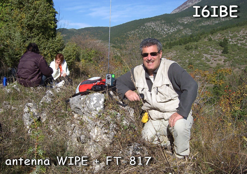
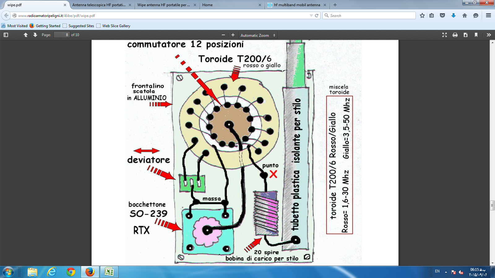
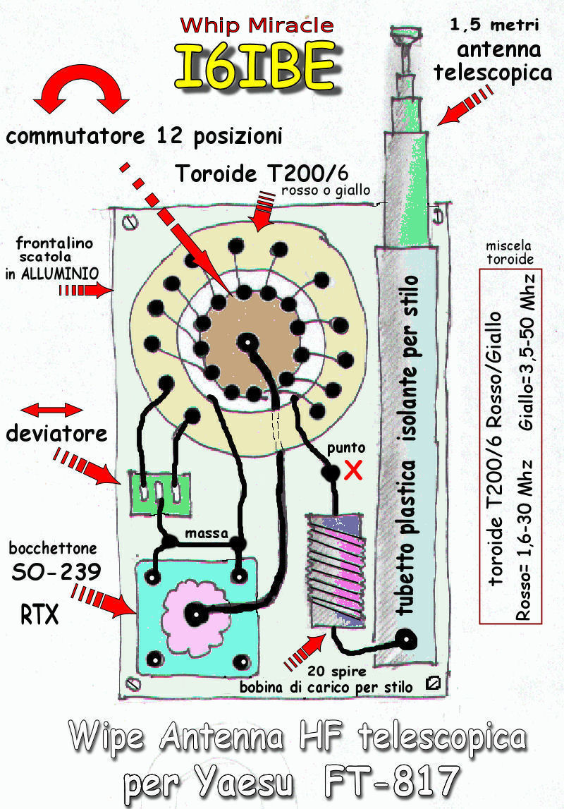
.JPG)




.jpg)


